Download
1 / 30
300 likes | 378 Views
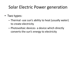
This study delves into the design and principles for demonstrating electric power generation using fusion reactors, outlining essential missions, operational requirements, and plasma performance analysis methods.

E N D
Conceptual Study on a Fusion Power Reactor for Early Demonstration of Electric Generation. Y. ASAOKA, R. HIWATARI and K. OKANO CRIEPI, Central Research Institute of Electric Power Industry, JapanUS-Japan Workshop on Fusion Power Plants and Related Advanced Technologies with EU Participation UCSD, San Diego, US, October 9-11, 2003
Demonstration of power generation • Missions of the Demonstration Reactor for Electric Power Generation. • To generate net electric power. (gross electric power > circulation power) • Steady and continuous operation. (tritium self-sufficiency and maintainability) • Licensing as a power plant.
Principles for Demo-CREST design • Minimum extension from the ITER. • Penet > 0 must be guaranteed with minimum extension from ITER plasma parameters. • Engineering designs are based on minimum extension from ITER engineering design and operation, and ITER test blanket modules. Materials to be developed in parallel with ITER are taken into accounts. • Flexibility to increase net electric power. • Electric power as a scale of commercial use can be generated with advanced plasma parameters attainable during the ITER operation and with advanced technologies and materials. • Reasonable plant construction cost. • Unit cost of electricity is not so important. However, the construction and operation cost must be reasonable in order to achieve public acceptance.
Minimum extension from the ITER • The net electric power output with almost achievable plasma performance and engineering techniques through the ITER program. • The electric break-even condition (Penet=0 MW) is achieved with the same plasma performance as the ITER reference operation mode (bN≦1.9, HH≦1.0, fnGW≦0.85). • Total NBI input power is restricted to 200 MW from the consideration of unit NBI input power and maximum port number on the vacuum vessel. • Plasma current ramp-up is entirely provided with magnetic flux of CS coils. • The maximum magnetic field 16 T is considered according to the outlook Nb3Al obtained, for example, in JAERI. • Thermal efficiency 30% is considered on the basis of the design of ITER test blanket modules. • NBI system efficiency 50% is considered according to the outlook obtained through the ITER R&D activities.
Demonstration of power generation • Missions of the Demonstration Reactor for Electric Power Generation. • To generate net electric power. (gross electric power > circulation power) • Steady and continuous operation. (tritium self-sufficiency and maintainability) • Licensing as a power plant.
Required Pf and Q for power generation • Thermal Efficiency: 30 %, • Plasma heating system efficiency (NBI): 50 %, • Maximum plasma heating power: 200 MW, • Recirculation power (excl. plasma heating): 60 MW, • Neutron coverage of the blanket: 90 %, • Neutron energy multiplication factor of the blanket: 1.2,
Analysis method of required plasma performance Parameter Region • Database of more than 100,000 operation points* for a tokamak reactor withFUSAC**. • Operation points* • Plasma size(major radius, aspect ratio), major physical parameters, shape and location of reactor component (TF & CS coil, radial build), weight of each component, construction cost, cost of electricity, fusion power, electric power. • FUSAC** • FUsion power plant System Analysis Code. • 0D plasma model of ITER Physics Guidelines. • Simple engineering model based on TRESCODE (JAERI). • Generomak Model for economic analysis. • The required region ofbN, fnGW, HHfor Penet=0〜1000MW.
Required plasma performance (1) R = 8.5 m • R = 8.5 m • Penet=0 MW • (Pf ~ 1,000 MW) • bN > 1.5, HH > 1.0 • Penet=600 MW • (Pf ~ 3,000 MW) • bN > 3.0, HH > 1.15 • In comparison with the present ITER experimental plan, • the outlook of both Penet =0 MW and Penet=600 MW will be obtained.
Required plasma performance (2) R = 7.5 m • R = 7.5 m • Penet=0 MW • (Pf ~ 1,000 MW) • bN > 1.9, HH > 1.0 • Penet=600 MW • (Pf ~ 3,000 MW) • bN > 3.4, HH > 1.15 • In comparison with the present ITER experimental plan, • the outlook of both Penet =0 MW and Penet=600 MW will be obtained.
Required plasma performance (3) R = 6.5 m • R = 6.5 m • Penet=0 MW • (Pf ~ 1,000 MW) • bN > 2.3, HH > 1.0 • Penet=600 MW • (Pf ~ 3,000 MW) • bN > 3.8, HH > 1.15 • In comparison with the present ITER experimental plan, the outlook of Penet =0 MW will be obtained, but it is difficult to achieve Penet=600MW.
Plasma size and required performance • The plasma size can be decreased with the progress on plasma performance. • R (m) 8.5 7.5 6.5 • Penet=0 MW bN 1.5 1.9 2.3 • (Pf~1,000 MW)HH 1.0 1.0 1.0 • Penet=600 MW bN 3.0 3.4 3.8 • (Pf~3,000 MW)HH 1.15 1.15 1.15 • Thermal efficiency 30%, NBI system efficiency 50%, Max. magnetic field 16T.
Operational region on R-A map • Penet = 0 MW case • Applied conditions • bN≦1.9 • HH≦1.0 • fnGW≦0.85 • yramp-up ≦ yCS • Flexibility for operation plasma current • Demo-CREST plasma configuration: R = 7.25 m, A = 3.4
Operation points on Q-Pf map • R= 7.25 m case
Plasma Parameters for OP1-4 • OP1 OP2 OP3 OP4 RS (optional) • bN 1.9 2.5 3.0 3.4 4.0 • RP (m)/A 7.25/3.4 ← ← ← ← • k/d 1.85/0.35 ← ← ← ← • Ip (MA) 15.9 15.4 15.6 14.7 14.0 • fbs (%) 23.7 34.4 40.1 49.7 56.1 • qy 5.0 5.0 5.0 5.2 5.2 • q0/qmin 1.3/- 1.7/- 2.1/- 2.3/- 3.5/2.9 • bp 1.11 1.55 1.86 2.15 2.42 • Bt (T) 8.0 8.0 8.0 7.8 7.2 • <Te> (keV) 17.9 18.7 20.7 18.4 18.1 • <Ti> (keV) 18.8 19.5 21.5 19.2 19.0 • Zeff 1.7 1.7 2.1 2.1 2.1 • <ne> (1020/m3) 0.625 0.789 0.873 1.05 1.11 • fnGW 0.56 0.73 0.80 1.02 1.12 • H/HH98 1.5/0.96 1.7/1.1 1.9/1.2 2.0/1.2 2.2/1.3 • Eb (MeV) 1.5 1.5 1.5 1.5 1.5 • PNBI (MW) 188 190 185 191 160 • on axis 164 163 157 166 118 • off axis 24 27 28 25 42 • Pf (MW) 1260 1940 2460 2840 2850 • Q 6.7 10.2 13.3 14.9 17.8
Electric power of Demo-CREST for OP1-4 • OP1 OP2 OP3 OP4 • Major radius, R (m) 7.25 • Aspect ratio, A 3.4 • Normalized beta, bN 1.9 2.5 3.0 3.4 • HH factor, HH 0.96 1.1 1.2 1.2 • Ratio to GW limit, fnGW 0.63 0.79 0.87 1.02 • NBI power, PNBI (MW) 188 190 185 191 • Energy multiplication, Q 6.7 10.2 13.3 14.9 • Fusion power, Pf (MW) 1,260 1,940 2,460 2,840 • Thermal output, Pth (MW) 1,470 2,180 2,720 3,100 • hth=30%, hNBI=50% • Pe, gross (MW) 440 650 810 940 • Pe, net (MW) 30 230 490 550 • hth=40%, hNBI=60% • Pe, gross (MW) 590 870 1,090 1,250 • Pe, net (MW) 330 600 810 960 • Mean wall load Pw (MW/m2) 1.1 1.8 2.2 2.6
Demonstration of power generation • Missions of the Demonstration Reactor for Electric Power Generation. • To generate net electric power. (gross electric power > circulation power) • Steady and continuous operation. (tritium self-sufficiency and maintainability) • Licensing as a power plant.
Demonstration of tritium self-sufficiency • Tritium self-sufficiency, net TBR > 1, which is indispensable for steady and continuous operation, is one of the most important missions of the power generation demonstration device. • Advantage of fusion energy on the energy security must be shown by demonstration of tritium self-sufficiency. • Breeding blankets are going to be set in the ITER as test blanket modules. However, it may be difficult to obtain a secure proof of net TBR > 1 for the next device. • Therefore, the blanket design of the demonstration reactor must have a large margin in tritium breeding. • Fusion power and size of device (neutron wall loading) • Thermal efficiency (temperature of coolant) • Blanket structure (neutron coverage of blanket) • Structure material development (design window of blanket)
Tritium breeding blanket • Design of the tritium breeding blanket of the Demo-CREST must be conservative, similar to the plasma parameters. • It must be based on one of the ITER test blanket module designs. • Design target is 3GW in fusion power (OP4). • Neutron wall load in the device of R=7.25 and A=3.4 is approximately 2.7 MW/m2 in average, 4.2 MW/m2 in peak. Mean heat load is approximately 0.68 Mw/m2. • Materials • Solid breeder(Li2TiO3)/Be/RAF/Water structure. • Restrictions and conditions • Maximum temperature of RAF: 723 K • Maximum temperature of Li2TiO3: 1023 K • Maximum temperature of Be: 723 K • Neutron wall load: 2.7 MW/m2 • Heat load on first wall: 0.68 MW/m2 • Blanket coolant temperature: 603 K
Radial build of the breeding blanket • Based on the ITER Test Blanket Module • Local TBR : 1.48 • Neutron energy multiplication factor : 1.31 • Li2TiO3 / Be ratio : 12.5 / 87.5 • (Li2TiO3: 85 %TD and 80 %PF, Be: 95 %TD and 80 %PF) • Li-6 enrichment: 90 %
Tritium breeding ratio and temperature distribution • Accumulative tritium breeding ratio • Temperature distribution • Limit of beryllium temperature restricts the blankets structure. Temperature of Li2TiO3 is lower than 900K.
Blanket structure (1: small modules) • Small blanket modules and vehicle type maintenance devices (ITER like) • Flexibility to replace a small part of blankets, (e.g. accidentally damaged modules, modules exposed to peak wall load) • Long maintenance period to replace all (or a large part of) blankets. • Small modules due to handling weight limit. • A large number of modules. • Large number of procedures including pipe re-connection and connection. • Reduction of the net TBR. • Gaps between modules, structure materials of blanket side wall and dead space due to curved surface of the blanket and module shape for front access. • In the case of Demo-CREST (larger than the ITER), • Number of modules is larger than that of the ITER. • On the basis of ITER technology.
Size of blanket modules & required local TBR • Simple evaluation of required local TBR by neutron coverage ratio of breeding zone in the blanket. • Size of blanket module 1m×1m 1.5m×1.5m 2m×2m • Ratio in surface area • Blanket • gaps between modules 0.017 0.018 0.011 0.012 0.008 0.009 • side wall of modules 0.098 0.104 0.066 0.070 0.050 0.053 • coolant headers in modules 0.079 0.084 0.054 0.057 0.041 0.043 • ribs between breeding zone 0.014 0.015 0.020 0.021 0.023 0.025 • holes for front accessing 0.014 0.015 0.006 0.007 0.004 0.004 • breeding zone 0.628 0.665 0.692 0.733 0.724 0.766 • sub total 0.850 0.900 0.850 0.900 0.850 0.900 • Divertor, duct, others 0.150 0.100 0.150 0.100 0.150 0.100 • Required local TBR • in the case of net TBR=1.00 1.593 1.505 1.445 1.365 1.382 1.305 • in the case of net TBR=1.05 1.673 1.580 1.517 1.433 1.451 1.370 • in the case of net TBR=1.10 1.753 1.655 1.590 1.501 1.520 1.436
Blanket structure (2: large module) • Large sector blankets and cask type maintenance devices • (CREST, DREAM, ARIES-RS,…. ) • Short maintenance period. • High net TBR can be expected. • Difficulty of accurate handling of large weight components. • Requirement of large TF coils. • Replacement of the whole blankets (and divertors) regardless to wall load distribution or components life time. • Extension from the ITER Technology.
ITER port shield (shield plug) • Minimum extension from the ITER. • ITER port shield: • Removable shield placed at backward of the test blanket modules or other components at horizontal port. • The weight is approximately 40 tons. • Removed and transferred by cask type handling device.
Blanket structure of the Demo-CREST • Similar procedures to large sector blanket system. • Large maintenance port (horizontal port). • 14 large TF coils. • Blanket of one sector, 1/14 of torus, is divided to three parts, outboard, inboard and upper. • The weight of the outboard blanket is approximately 40 tons. Those of the inboard blanket and the upper blanket are around 15 to 20 tons.
Maintenance procedures • Procedures of blanket replacement • Straight withdrawal of the outboard and inboard blankets through each horizontal maintenance port. • Take down the upper blankets to mid-plane level, and withdraw through each horizontal port. Although weight of the upper blanket is larger than that of ITER blanket modules, the flexibility of handling to the toroidal direction. • Outboard shields handling and support of the outboard blanket • Outboard shield, which must be removed to open the maintenance port, is divide to three parts. Weight of outboard shield to be removed is approximately 126 tons. Therefore weight of each part is 42 tons. • As the outboard blanket and the outboard shields must be withdrawn separately,the outboard blanket is supported independently by the ring shield (see next sheet), not supported by the outboard shield. • Replacement of the divertors • The interval of divertor replacement is considered to be different from that of the blanket. The divertors can be replaced independently with similar procedure to the ITER divertor maintenance.
Elevation view and plane view • Procedure of the outboard blanket replacement is the simplest. • Replacement of the blankets according to wall load distribution.
Summary • We have started conceptual study on a fusion power reactor for early demonstration of the electric generation. • Demonstration of electric power generation (Pe,net > 0) is possible with minimum extension from the ITER plasma parameters, the ITER technologies, and materials to be developed in parallel with the ITER. • And… • Up to 3GW fusion power in R=7.25m, A=3.4 device. • Possibility to obtain 1,000 MWe with advanced plasma parameters and advanced technologies. • Blanket concept based on the ITER test blanket module consists of Li2TiO3, Be, pressurized water and reduce activation ferritic steel. The local TBR and neutron energy multiplication factor are 1.48 and 1.31, respectively. • The concept of blanket structure and maintenance procedure can secure the tritium self-sufficiency and maintainability, which are indispensable to demonstrate steady and continuous operation. Reduction of the blanket replacement period and the replacement according to the wall load distribution would be possible.
For details • Please refer to our recent papers: • “Plasma PerformanceRequired for a Tokamak Reator to Generate Net Electric Power” • R. Hiwatari, K. Okano, Y. Asaoka Y. Yoshida, K. Tomabechi • J. Plasma Fusion Res., Vol.78, No.10 (2002) 911-913 • “Stability of Beam Driven Equilibria with a Closed Stablization Wall” • K. Okano, R. Hiwatari, Y. Asaoka • J. Plasma Fusion Res., Vol 79, No.6 (2003) 546-548