Comprehensive Guide to Assembly and Linking in Software Development
Explore the last phases of compilation: HLL to assembly, linking, and execution processes. Learn about assemblers, symbolic instructions, symbol tables, and dynamic linking in software development.


Comprehensive Guide to Assembly and Linking in Software Development
E N D
Presentation Transcript
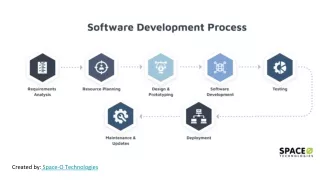
Asm. File C File C File Compiler Assembler Binary File Binary File Binary File Linker Debugger Exec. File Profiler Verification Phase Implementation Phase Library Software Development Process • Compilers • Cross compiler • Runs on one processor, but generates code for another • Assemblers • Linkers • Debuggers • Profilers
Assembly and linking • Last steps in compilation: HLL compile assembly HLL assembly assemble HLL assembly load link executable
Multiple-module programs • Programs may be composed from several files. • Addresses become more specific during processing: • relative addresses are measured relative to the start of a module; • absolute addresses are measured relative to the start of the CPU address space.
Assemblers • Major tasks: • generate binary for symbolic instructions; • translate labels into addresses; • handle pseudo-ops (data, etc.). • Generally one-to-one translation. • Assembly labels: ORG 100 label1 ADR r4,c
ADD r0,r1,r2 xx ADD r3,r4,r5 CMP r0,r3 yy SUB r5,r6,r7 assembly code xx 0x8 yy 0x10 symbol table Symbol table
Symbol table generation • Use program location counter (PLC) to determine address of each location. • Scan program, keeping count of PLC. • Addresses are generated at assembly time, not execution time.
ADD r0,r1,r2 xx ADD r3,r4,r5 CMP r0,r3 yy SUB r5,r6,r7 xx 0x8 PLC=0x7 PLC=0x7 PLC=0x7 PLC=0x7 Symbol table example yy 0x10
Two-pass assembly • Pass 1: • generate symbol table • Pass 2: • generate binary instructions
Relative address generation • Some label values may not be known at assembly time. • Labels within the module may be kept in relative form. • Must keep track of external labels---can’t generate full binary for instructions that use external labels.
Pseudo-operations • Pseudo-ops do not generate instructions: • ORG sets program location. • EQU generates symbol table entry without advancing PLC. • Data statements define data blocks.
Linking • Combines several object modules into a single executable module. • Jobs: • put modules in order; • resolve labels across modules.
xxx ADD r1,r2,r3 B a yyy %1 a ADR r4,yyy ADD r3,r4,r5 entry point external reference Externals and entry points
Module ordering • Code modules must be placed in absolute positions in the memory space. • Load map or linker flags control the order of modules. module1 module2 module3
Dynamic linking • Some operating systems link modules dynamically at run time: • shares one copy of library among all executing programs; • allows programs to be updated with new versions of libraries.
S00F000068656C6C6F202020202000003C S11F00007C0802A6900100049421FFF07C6C1B787C8C23783C6000003863000026 S11F001C4BFFFFE5398000007D83637880010014382100107C0803A64E800020E9 S111003848656C6C6F20776F726C642E0A0042 S5030003F9 S9030000FC Record Description Address Bytes Data Sequence S0 Block header 2 Yes S1 Data sequence 2 Yes S2 Data sequence 3 Yes S3 Data sequence 4 Yes S5 Record count 2 No S7 End of block 4 No S8 End of block 3 No S9 End of block 2 No Formato S
:10010000214601360121470136007EFE09D2190140 :100110002146017EB7C20001FF5F16002148011988 :10012000194E79234623965778239EDA3F01B2CAA7 :100130003F0156702B5E712B722B732146013421C7 :00000001FF The first data record is explained as follows: : Start code. 10 Hex 10 (decimal 16), indicating 16 data character pairs, 16 bytes of binary data, in this record. 01 Four-character 2-byte address field: hex address 0100, 00 indicates location where the following data is to be loaded. 00 Record type indicating a data record. The next 16 character pairs are the ASCII bytes of the actual program data. 40 Checksum of the first Hex-record. The termination record is explained as follows: : Start code. 00 Byte count is zero, no data in termination record. 00 Four-character 2-byte address field, zeros. 00 01 Record type 01 is termination. FF Checksum of termination record. HEX-RECORD TYPESThere are three possible types of Hex-records. 00 :A record containing data and the 2-byte address at which the data is to reside. 01 : A termination record for a file of Hex-records. Only one termination record is allowed per file and it must be the last line of the file. There is no data field. 02 : A segment base address record. This type of record is ignored by Lucid programmers. Intel HEX file