Download
1 / 20
200 likes | 279 Views
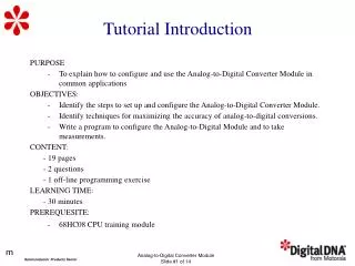
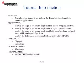
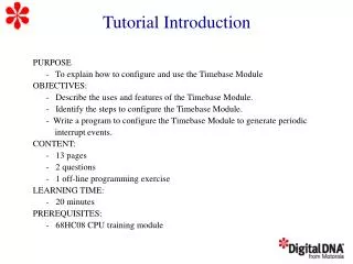
Tutorial Introduction. PURPOSE: To explain MCU processing of reset and and interrupt events OBJECTIVES: Describe the differences between resets and interrupts. Identify different sources of resets and interrupts. Describe the MCU reset recovery process.

E N D
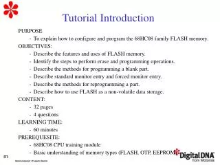
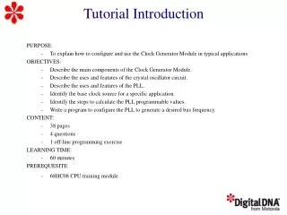
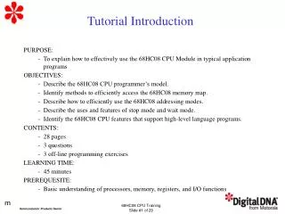
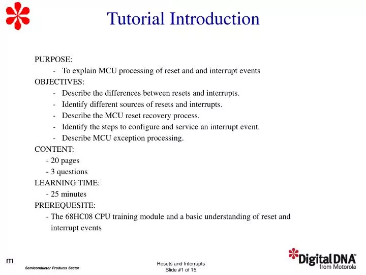
Tutorial Introduction • PURPOSE: • To explain MCU processing of reset and and interrupt events • OBJECTIVES: • Describe the differences between resets and interrupts. • Identify different sources of resets and interrupts. • Describe the MCU reset recovery process. • Identify the steps to configure and service an interrupt event. • Describe MCU exception processing. • CONTENT: • - 20 pages • - 3 questions • LEARNING TIME: • - 25 minutes • PREREQUESITE: • - The 68HC08 CPU training module and a basic understanding of reset and • interrupt events
Resets and Interrupts Overview • Reset sources: - External - power on, reset pin driven low - Internal - COP, LVI, illegal opcode, illegal address • Resets initialize the MCU to startup condition. • Interrupt sources: - Hardware - Software • Interrupts vector the program counter to a service routine.
Internal Reset Sources ILLEGAL ADDRESS RST ILLEGAL ADDRESS RST ILLEGAL OPCODE RST ILLEGAL OPCODE RST INTERNAL RESET INTERNAL RESET (RST) COPRST COPRST LVI LVI POR POR
SIM Reset Status Register (SRSR) POR — Power-On Reset Flag 1 = Power-on reset since last read of SRSR 0 = Read of SRSR since last power-on reset
32 CYCLES 32 CYCLES Internal Reset Timing PULLED LOW BY MCU RST PIN 32 CYCLES 32 CYCLES CGMXCLK INTERNALRESET
Interrupt Processing Overview • Hardware Interrupt • Initiated by hardware pin or Module • Uses an interrupt vector and a service routine • Can be masked • Software Interrupt (SWI) • Executed as part of the instruction flow • Processed like a hardware interrupt • Can’t be masked
Hardware Interrupt Sources • IRQ pin • I/O port pins • Timer Interface Module (TIM) • SCI/SPI ports
Interrupt Sources Vector Address Source Flag Mask INT Reg Flag Priority TBIF TBIE IF16 16 $FFDC - $FFDD TimeBase COCO AIEN IF15 15 $FFDE - $FFDF ADC Conv. Complete KEYF IMASKK IF14 14 $FFE0 - $FFE1 Keyboard Pin TC IF13 13 $FFE2 - $FFE3 SCI Trans. Complete TCIE SCTE SCI Transmitter Empty SCTIE IDLE IF12 12 $FFE4 - $FFE5 SCI Input Idle ILIE SCI Receiver Full SCRF SCRIE $FFE6 - $FFE7 SCI Receiver Overrun OR ORIE IF11 11 SCI Noise Flag NF NEIE SCI Framing Error FE FEIE SCI Parity Error PE PEIE SPTE SPTIE IF10 10 $FFE8 - $FFE9 SPI Transmitter Empty $FFEA - $FFEB SPI Receiver Full SPRF SPRIE IF9 9 SPI Overflow OVRF ERRIE SPI Mode Fault MODF ERRIE TOF TOIE IF8 8 $FFEC - $FFED TIM2 Overflow CH1F CH1IE IF7 7 $FFEE - $FFEF TIM2 Channel 1 CH0F CH0IE IF6 6 $FFF0 - $FFF1 TIM2 Channel 0 TIM1 Overflow TOF TOIE IF5 5 $FFF2 - $FFF3 TIM1 Channel 1 CH1F CH1IE IF4 4 $FFF4 - $FFF5 TIM1 Channel 0 CH0F CH0IE IF3 3 $FFF6 -$FFF7 PLL PLLF PLLIE IF2 2 $FFF8 - $FFF9 IRQ IRQF IMASK1 IF1 1 $FFA - $FFFB SWI None None None 0 $FFFC - $FFFD Reset None None None 0 $FFFD - $FFFF
Context Switching Recognition Arbitration Stacking - Saving Context (set I-bit = 1) Vector Fetching Interrupt Servicing
Recognition • Resets • - Recognized and acted on immediately • Interrupts • - Recognized during last cycle of current instruction • - Acted on after last cycle of the current instruction
Arbitration Source Priority TimeBase 16 ADC Conv. Complete 15 Keyboard Pin 14 SCI Trans. Complete 13 SCI Transmitter Empty SCI Input Idle 12 SCI Receiver Full 11 SCI Receiver Overrun SCI Noise Flag SCI Framing Error SCI Parity Error SPI Transmitter Empty 10 9 SPI Mode Fault SPI Overflow SPI Mode Fault 8 TIM2 Overflow TIM2 Channel 1 7 TIM2 Channel 0 6 5 TIM1 Overflow 4 TIM1 Channel 1 3 TIM1 Channel 0 2 PLL 1 IRQ SWI 0 Reset 0 L H
Stacking SP SP SP PC_H X A SP Stack Pointer CCR 5 4 3 2 1 SP Stacking Order PC_L
Vector Address Source $FFDC - $FFDD TimeBase $FFDE - $FFDF ADC Conv. Complete $FFE0 - $FFE1 Keyboard Pin $FFE2 - $FFE3 SCI Trans. Complete SCI Transmitter Empty $FFE4 - $FFE5 SCI Input Idle SCI Receiver Full $FFE6 - $FFE7 SCI Receiver Overrun SCI Noise Flag SCI Framing Error SCI Parity Error $FFE8 - $FFE9 SPI Transmitter Empty $FFEA - $FFEB SPI Receiver Full SPI Overflow SPI Mode Fault $FFEC - $FFED TIM2 Overflow $FFEE - $FFEF TIM2 Channel 1 $FFF0 - $FFF1 TIM2 Channel 0 TIM1 Overflow $FFF2 - $FFF3 TIM1 Channel 1 $FFF4 - $FFF5 TIM1 Channel 0 $FFF6 -$FFF7 PLL $FFF8 - $FFF9 IRQ $FFA - $FFFB SWI $FFFC - $FFFD Reset $FFFD - $FFFF Vector Fetching
Executing Exception Handler SP SP SP SP CCR A PC_H X SP SP PC_L Stack Pointer 7 Exception Handler H 6 L PSHH 5 4 3 2 1 Stacking Order H
Restoring Old Context SP SP SP SP CCR X A PC_H SP PC_L Stack Pointer Exception Handler PSHH H Unstacking Order 1 L 2 3 4 5 6 PULH RTI H
Example: Unused Interrupts Trap • ;* Using a “Trap” with a COP Watchdog • ;* Unused Vectors • TRAP: • bra TRAP ; wait for a COP reset • org $1FF8 ; Timer Vector • fdb TRAP ; Points to TRAP • org $1FFC ; Software Interrupt • fdb TRAP ; Points to TRAP
Question Which of the following exceptions can’t be masked? Click on your BEST choice. a) Software interrupts b) TIM overflow c) SCI parity error d) Internal resets e) b and c f) a and d
Question When does the interrupt service routine begin executing? Click on your choice. a) Immediately b) In the next clock cycle c) After the current instruction is finished executing d) During last cycle of the current instruction
Question If these five hardware interrupts occurred at the same time, which interrupt event would be serviced first? Click on your choice. a) SCI Receiver Full b) PLL c) IRQ d) TIM 2 Channel 0 e) ADC Conversion Complete
Tutorial Completion • - Reset and Interrupt Sources • - Reset Recovery • - MCU Exception Processing • - Interrupt Servicing