Download
1 / 41
430 likes | 603 Views
Engineering 36. Chp 10: Beams-1. Bruce Mayer, PE Licensed Electrical & Mechanical Engineer BMayer@ChabotCollege.edu. Introduction. In Previous Chapters We Examined Determining External Forces Acting On A Structure Loads & Reactions

E N D
Engineering 36 Chp 10:Beams-1 Bruce Mayer, PE Licensed Electrical & Mechanical EngineerBMayer@ChabotCollege.edu
Introduction • In Previous Chapters We Examined • Determining External Forces Acting On A Structure • Loads & Reactions • Determining Forces Which Hold Together The Various Members Of A Structure • Trusses & Machines (at PIN Joints) • Next, We Learn How to Determine The Internal Forces Which Hold Together The Various Parts Of A Given Member
Introduction (2) • The Four Types of INTERNAL Forces Present in Structural Members • Tension or Compression • Shear • Bending • Torsion/Twisting • The Subsquent Analyses do Not Consider Torsion Loads • For More Torsion Info See ENGR45
Introduction (3) • Examine in Detail Two Important Types Of Engineering Structures: • BEAMS - usually long, straight, prismatic (constant cross-section) members designed to support loads applied at various points along the member • CABLES - flexible members capable of withstanding only tension, designed to support concentrated or distributed loads
Internal Forces in Members • (a) Straight two-force member AB is in equilibrium under application of F and −F. • (b) Internal Forces equivalent to F and −F are required for equilibrium of free-bodies AC and CB. Also Called N VIRTUAL Section
Internal Forces in Members (2) • Multiforce member ABCD is in equil-ibrium under the application of cable and member (pin) contact forces. FBD VIRTUAL Section J • INTERNAL forces equivalent to a FORCE-COUPLE (F/V-M) system are necessary for equilibrium of free-bodies JD and ABCJ
Internal Forces in Members (3) • An internal FORCE-COUPLE (F/V-M or N/V-M) system is required for equilibrium of TWO-FORCE members which are NOT STRAIGHT
Example: Beam in Frame • Given 3-Member Structure at Left • Determine the INTERNAL forces in • member ACF at point J • member BCD at point K • Note
Example: Beam in Frame • Cut member ACF at J. • The internal forces at J are represented by equivalent force-couple (F/V-M or N/V-M) system which is determined by considering equilibrium of either cut part. • Cut member BCD at K. • Determine force-couple (F/V-M or N/V-M) system equivalent to internal forces at K by applying equilibrium conditions to either cut part. • Solution Plan: • Compute Rcns and Forces at connections for each member
Example: Beam in Frame • First Determine External Rcns & Connection-Forces • Consider the ENTIRE Frame as a rigid Free Body
Example: Beam in Frame • Consider Link Member BCD as a Free Body Don’t Know (yet)
Example: Beam in Frame • Consider ABE as a Free Body • Recall from Member BCD • But from Above Bx = 0 • ALL Forces on ACF arenow KNOWN
Example: Beam in Frame • Cut member ACF at J • The internal forces at J are represented by an equivalent force-couple system • Consider Free Body AJ
Example: Beam in Frame • Cut member BCD at K • Determine a force-couple system equivalent to internal forces at K • Consider Free Body BK
3D Internal Forces • Full 3D Loading: • For Structural Analysis (ENGR45) need: • Axial Force, Ny • Torsional Moment, My • TOTAL Shear Magnitude • TOTAL Bending Moment Magnitude
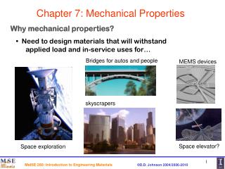
Beam – What is it? • Beam Structural member designed to support loads applied at various points along its length • Beams can be subjected to CONCENTRATED loads or DISTRIBUTED loads or a COMBINATION of both. • Beam Design is 2-Step Process • Determine Axial & Shearing Forces and Bending Moments Produced By Applied Loads • Select Structural Cross-section & Material Best Suited To Resist SHEARING-Forces and BENDING-Moments
Beam Loading and Supports • Beams are classified according to the Support Method(s); e.g., Simply-Supported, Cantilever • Reactions at beam supports are Determinate if they involve exactly THREE unknowns. • Otherwise, they are Statically INdeterminate
Shear & Bending-Moment • Goal = determine bending moment and shearing force at any point, say C, in a beam subjected to concentrated and distributed loads • Determine reactions at supports by treating whole beam as a free-body. • Cut beam at C and draw free-body diagrams for AC and CB exposing V-M System • From equilibrium considerations, determine M & V or M’ & V’.
Consider a Typical-Case (Gravity) Loaded Simply-Supported Beam with the X-Axis Origin Conventionally Located at the LEFT 2D V & M Sign Conventions • Next Consider a Virtual Section Located at C • DEFINE this Case as POSITIVE • Shear, V • The Virtual Member LEFT of the Cut is pushed DOWN by the Right Virtual Member • Moment, M • The Beam takesBOWL Shape
2D V & M Sign Conventions (2) • Positive Shear • Right Member Pushes DOWN on Left Member • Positive Bending • Beam Concave UP • POSITIVE Internal Forces, V & M • Note that at a Virtual Section the V’s & M’s MUST Balance
With the Signs of V&M Defined we Can now Determine the MAGNITUDE and SENSE for V&M at ANY arbitrary Virtual-Cut Location PLOTTING V&M vs. x Yields the Stacked Load-Shear-Moment (LVM) Diagram V & M Diagrams LOAD Diagram “Kinks” at Load-Application Points SHEAR Diagram MOMENT Diagram
Determine reactions at supports Cut beam at C (distx) and consider left member AC Build V&M Diagram Cut beam at E and consider right member EB • Plot V vs x • Plot M vs x • Note: For a beam subjected to CONCENTRATED LOADS, shear is CONSTANT between loading points and moment varies LINEARLY
For the Given Load & Geometry, Draw the shear and bending moment diagrams for the beam AB Solution Plan Taking entire beam as free-body, calculate reactions at A and B. Determine equivalent internal force-couple systems at sections cut within segments AC, CD, and DB Plot Results Example: Torqued Beam
Example: Torqued Beam • Taking entire beam as a free-body, calculate reactions at A and B. • Note that the 400 lb load at E may be REPLACED by a 400 lb force and 1600 in-lb couple at D
Example: Torqued Beam • Evaluate equivalent internal force-couple systems at sections cut within segments AC, CD, and DB • For AC use Cut-1
Example: Torqued Beam • Evaluate equivalent internal force-couple systems at sections cut within segments AC, CD, and DB • For CD use Cut-2
Example: Torqued Beam • Evaluate equivalent internal force-couple systems at sections cut within segments AC, CD, and DB • For DB Use Cut-3
Example: Torqued Beam • Plot Results • From A to C: • From C to D • From D to B • Note that over A-C The Bending-Moment Equation isSECOND Order, and Concave DOWN
Axial Forces • In Civil Engineering Most Beams are loaded Transversely Relative to the Beam Axis • Most Beams do NOT have AXIAL Loads • In ME however, many beam-like structures (e.g., Shafts) have significant axial loads that accompany the transverse Shear-Force and Bending-Moment
When Significant Axial Loads are present in a Beam, An AXIAL-Force Diagram is added to the typical V&M Diagrams The “N” Diagram is typically placed ABOVE the V-diagram Axial Force Diagram
WhiteBoard Work Let’s WorkThese NiceProblems
Engineering 36 Appendix Bruce Mayer, PE Registered Electrical & Mechanical EngineerBMayer@ChabotCollege.edu
Bent Bar Prob • Determine at Pt-C the magnitudes of • Axial Force • Shear Force • Bending Moment • Torsional Moment • The Moment on the AC Axis
Beam Prob • For the Beam withLoading a shown: • Draw the SHEARand BENDING-MOMENTDiagrams • Determine the Largest-Magnitude Bending-Moment and its Location