Download
1 / 82
830 likes | 855 Views
Learn about fault-tolerant automation systems, the benefits they offer, and how they can help reduce production losses and ensure system reliability. Find out the different concepts and objectives of fault-tolerant systems in industrial applications.

E N D
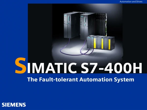
Automation and Drives S IMATIC S7-400H The Fault-tolerant Automation System
Different Concepts Redundant automation systems Overview Fault-tolerant 1-out-of-2 systems Objective: Reduce the probability of production losses by switching to a standby system Fail-safe 1-out-of-2 systems Objective: Protect life, the environment and investments by safely disconnecting to a secure “off” position
Overview • Why do we have fault-tolerant programmable logic controllers? • The objective of using high-availability programmable logic controllers is a reduction of production losses. It does not matter whether the losses are caused by an error or as a result of maintenance work. • The higher the costs of a stoppage, the more worthwhile it is to use a fault-tolerant system. The generally higher investment costs of fault-tolerant systems are quickly compensated by avoiding production losses.
Benefits Overview • Avoidance of control system failures due to individual faults • This is attained primarily through a redundant configuration • Fault-tolerance is required in the following cases: • When processing valuable materials • When downtimes or production failures would be expensive • When a control system failure would result in high restart costs • In order to enable operation without supervisory or maintenance personnel
Software redundancy In a large number of applications, requirements for the quality of redundancy or the number of system sections that necessitate redundant PLCs are not high enough to warrant the use of a specific fault-tolerant system. Frequently, simple software mechanisms are sufficient to allow continuation of a failed control task on a substitute system in the event of an error. The “SIMATIC S7 Software Redundancy” options software can run on S7-300 and S7-400 standard systems to control processes that tolerate transfer times to a substitute system within seconds, such as water works, water treatment systems or traffic flows. Overview
Overview • Hardware Redundancy • For Fast Processes Switch Over time : few M. Sec. • Software Redundancy • For Slow Processes Switch Over time : few Sec.
Industries (1) Overview • Power generation and distribution(oil, gas, electricity) • Power plants • Pipelines • Offshore • District heating systems • Chemical, electrochemical, petrochemical and pharmaceutical industries • Mining • Environmental engineering • Water treatment • Refuse incineration • Pulp and paper • Steel and metal
Industries (2) Overview • Food and beverages • Glass industry • Semiconductor industry (utilities) • Transport • Tunnel automation • Marine automation • Airports • Runway lighting • Baggage transport
System architecture Overview Clients Parallel redundancy Management level Server Parallel redundancy With archive-matching PC network/terminal bus Fault-tolerantcommunication Ethernet Media redundancy Process level H CPUs Hot stand-by SW redundancy Warm stand-by Redundant power supply ET 200M Field level Redundant PROFIBUS Redundant IM 153
System integration Overview • Hidden redundancy • Transparent programming(programming same as for non-redundant systems) • Standard system parameterization • Standard handling • All SIMATIC programming languages can be used without restriction • Platform for F andFH systems
ConfigurationRedundant link Replaceable Sync modules Fiber-optics (FO) Configuration Fiber-optics (FO)
Hardware of the S7-400H base system: Minimum Configuration Central processing units At the heart of the S7-400H are the two central processing units. Setting of the synchronization submodules, which have to be plugged into the CPU, defines the rack numbers. In the following we will refer to the CPU in rack 0 as CPU 0,and to the CPU in rack 1 as CPU 1.
ConfigurationHighlights new CPUs • Performance Increase • Average Increase 417-4H appr. x 2,5-3 414-4H appr. x 1,2-2,2 • More Memeory 417-4H from 4 MB to 20MB 414-4H from 768KB to 1,4MB Higher Reliability • Memory with automatic Error Detection and Correction (EDC) New Feature • Distance between the Controller up to 10km (before 500m) Konfiguration
ConfigurationTechnical specifications for the CPUs • Two CPU types available • CPU 417-4H with 20MB onboard • CPU 414-4H with1,4MB onboard • General technical specifications,e.g. CPU 417-4 or CPU 414-3 • 4 integrated interfaces • Two for the Sync modules • One DP interface • One MPI/DP interface Configuration
Central Controller Configuration • Distance between the Controller up to 10m • Use of the Sync-Modules for Patch Cables up to 10m • MLFB Module: 6ES7 960-1AA04-0XA0 • MLFB FO-Cable 1m: 6ES7 960-1AA04-5AA0 • MLFB FO-Cable 2m: 6ES7 960-1AA04-5BA0 • MLFB FO-Cable 10m: 6ES7 960-1AA04-5KA0 • Distance between the Controller up to 10km • Use of the Sync-Modules for Cables up to 10km • MLFB Module: 6ES7 960-1AB04-0XA0 • Monomode FO-Cable LC/LC Duplex crossed 9/125µ Konfiguration
Expanding the Working Memory of the CPU 417-4 H with Memory Modules
Expanding the Working Memory of the CPU 417-4 H with Memory Modules
Mounting rack for S7-400H • It is recommended that you use the UR2-H mounting rack for the S7- • 400H. The mounting rack makes it possible to configure two • separate subsystems, each containing nine slots, and is suitable for • installation in 19” cabinets. • Alternatively, you can also configure the S7-400H on two separate • mounting racks. • Two mounting racks, the UR1 and UR2, are available for this purpose.
Central controller configurations • With two standard subracks Redundant power supply (PS) optional PS PS CPU PS PS CPU Max. cable length 10km With H subrack (with split backplane bus) Configuration PS PS CPU PS PS CPU
Power supply • As a power supply, you will require for each fault-tolerant CPU a • power supply module from the standard range of the S7-400. • Power supply modules for rated input voltages of 24 VDC and • 120/230 VAC are available with 10 and 20 A output current. • Redundant Power Supply • To enhance the availability of the power supply, you can also use two redundant power supplies in each subsystem. In this case you should use the PS 407 10A R power supply module for rated voltages of 120/230 VAC with an output power of 10 A. Configuration
What is single-channel, one-way I/O? • With the single-channel, one-way configuration single input/output modules are present (single-channel). The input/output modules are located in just one of the subsystems and are only addressed by that subsystem. • A single-channel, one-way I/O configuration is possible in • Central controllers and expansion units • Distributed I/Os • The single-channel, one-way I/O configuration is to be recommended for individual input/output channels for which normal availability of the I/O is sufficient. Configuration
Failure of the single-channel, one-way I/O • In the event of a malfunction the S7-400H with a single-channel, one-way I/O behaves like a standard S7-400 system, in other words: • When the I/O fails, the defective I/O is no longer available. • When a subsystem fails, the entire process I/O of that subsystem is not • available any more.
Using Single-Channel, Switched I/O • In Redundant mode they • may be addressed by both • subsystems. • In single mode, the master • subsystem can always • address all switched • I/O . Configuration
Using Single-Channel, Switched I/O • ET 200M distributed I/O device equipped with an active backplane bus and a redundant PROFIBUS-DP slave interface module IM 153-2 or IM 153-2FO. permissible IM are: • IM153-2: 6ES7 153-2AA02-0XB0 version 7 or later • IM 153-2FO: 6ES7 153-2AB01-0XB0 version 6 or later Configuration
Using Single-Channel, Switched I/O • Rules • When you use a single-channel, switched I/O, the configuration must • always be symmetrical, in other words: • The fault-tolerant CPU and other DP masters must be located in • identical slots and both subsystems (e.g. in slot 4 on both subsystems) • The DP masters must be connected on both subsystems to the same • integrated interface (e.g. to the PROFIBUS-DP interfaces of the two • fault-tolerant CPUs). Configuration
I/O configurationSwitched I/O Redundant IM 153-2 PROFIBUS DP ET 200M with active backplane bus L+ L+ Configuration Special bus module (BM) IM Active backplane bus IM
I/O configurationSwitched I/O: mode of operation • Both DP masters are active and functioning properly • Reading inputs:The inputs are read only from the preferred channelside (active IM) • Writing outputs:The data are accepted by both channels.Only the data in the preferred channel are forwarded to the outputs. Configuration
I/O configurationConnecting PROFIBUS PA via PA link PROFIBUS DP 2 x IM 157 DP-PA link Configuration
I/O configurationY-Link • The Y-link bus coupler creates a network portal from the redundant DP master system to a one-channel DP master system Rack 0 Rack 1 IM 153-2 with ET 200M Configuration IM 157 with PA bus Y-Link with DP bus
I/O configurationY-Link hardware configuration • IM 157: • 6ES7 157-0AA82-0XA0 • Y-Link: • 6ES7 197-1LB00-0XA0 • Bus module BM IM 157 • 6ES7 195-7HD80-0XA0 • Bus module BM Y-Link • 6ES7 654-7HY00-0XA0 • Collective Order No. • 6ES7 197-1LA02-0XA0 IM 157 Y-Link Configuration
I/O configurationY-Link configuration Configuration
Installation notes • Insert the synchronization submodules into the CPUs. Then screw up • the additional front bezels to activate them . • Connect the fiber-optic cables (always connect the two upper • synchronization submodules and the two lower synchronization • submodules of the CPUs). Lay the fiber-optic cable so that it is protected • from any damage. • Make sure with the route wires in addition that the two fiber-optic • cables are always laid so that they are isolated from each other. Laying • them separately enhances their availability and protects then from • potential dual faults in the event, say, of simultaneous interruption of • the fiber-optic cables. • In addition, make sure that the fiber-optic cables are plugged into the • two CPUs before turning on the power supply or turning on the system. • If they are not, the two CPUs might both process the user program as • master CPUs.
Installation notes • Connect the programming device to the first fault-tolerant CPU • (CPU0). This CPU should be the master CPU of the S7-400H. • A high-quality RAM test is performed after power on. It requires • approximately 8 seconds per megabyte of RAM. During this time the • CPU cannot be addressed via the multipoint interface and the STOP • LED flashes. If there is a backup battery, the test will not be • performed on further POWER ONs. • Perform a memory reset for both CPUs using the mode selector. This • applies the set mounting rack numbers of the synchronization • modules to the operating system of the CPU. • Switch the two CPUs of the S7-400H to STOP. Load the user program • into CPU0 • Start the S7-400H PLC by switching the mode selector, first for CPU0 • and then for CPU1, to RUN-P.
Installation notes • Result: • CPU0 starts up as the master CPU and CPU1 as the standby CPU. • After the link-up and update of the standby CPU the S7-400H switches to redundant system mode and executes the user program (run light on digital output module).
What does active redundancy mean? • Active redundancy, frequently referred to as functional redundancy • too, means that all redundant resources are constantly in operation • and are simultaneously involved in the execution of the control task. • This means for the S7-400H that the user program in the two CPUs is • completely identical and is executed simultaneously (synchronously) • by the two CPUs. • To identify the two subsystems, we use the traditional expressions of • “master” and “standby” for two-channel fault-tolerant systems in this • description. The standby always operates so that it is synchronized • with the events on the master. • The standby CPU switches to STOP mode in the event of the redundant • link failing, whereas the master CPU remains in RUN mode.
Redundancy principle (1) Redundancy with identical components(homogeneous redundancy) Redundancy features Majority redundancy Passive redundancy Active redundancy A B m-v-n A R 1 1-v-2 1-v-2 2oo2 2oo2 A B C Fault-tolerant Hot stand-by = automatic switchover < 100 ms Warm stand-by = automatic switchover in seconds range Redundancy principle S7-400H m-of-n Fault-tolerant and failsafe A B 2-v-2 A R 1-v-2 1oo2 HW or SW voting 2oo2 Cold stand-by = manual switchover Failsafe
Redundancy principle (2) Synchronization, information and status exchange Redundancy features IM IM DI DO AI AO FM Process
Bumpless master-stand-by switchover • Switchover time • Switchover time < 100ms • Outputs are retained during switchover • No information or alarm/interrupt is lost • Switchover criteria • Master failure • Power supply • Rack • Sync module • Sync cable • CPU • Failure of a DP string or DP slave interface module does not force a switchover Redundancy features • Switchover
Master/standby assignment • When the S7-400H is turned on for the first time, the first CPU to be stated up becomes the master CPU; the other CPU becomes the standby CPU. • Once the master/standby assignment has been established, it remains like that upon simultaneous POWER ON. • The master/standby assignment is modified by: • 1. The standby CPU starting before the master CPU (interval of at least 3 s) • 2. Failure or STOP of the master CPU in redundant system mode
Automatic event synchronization • Synchronization procedure Event synchronization Redundancy features No synchronization Cycle synchronization Time synchronization Command synchronization • Synchronization Subcontroller B Subcontroller A Subcontroller A Subcontroller B Subcontroller A Subcontroller A Subcontroller B Subcontroller B
Automatic event synchronization • Principle Redundancy features Synchronization, Information and status exchange • Synchronization A A I 10.0 I 10.0 S O 8.0 S O 8.0 : : : : : : Value Synchronization L PW100 L PW100 Ackn. L DW 10 L DW 10 + F + F Synchronization T PW130 Switchover :
CPU 1 CPU 0 Automatic event synchronization • Cycle Redundancy features • Synchronization Self-test Self-test PII exchange PII PII Synchronization User program User program Match-up PIO PIO
Automatic event synchronization • Customer benefits • Transparent programming • All standard SIMATIC-S7 programming languages • No command restrictions • Easy porting of the user programfrom standard CPU to fault-tolerant CPU • Bumpless switchover • No loss of information • No loss of alarms/interrupts • Because all redundancy-specific functions are handled by the operating system, the user can feel assured that he/she has done everything right as far as redundancy is concerned Redundancy features • Synchronization
Comprehensive self-test functions • Self-test • Scope: • CPU • Memory • Synchronization link • Organization: • Startup self-test • Complete test • Self-test in cyclic mode • Executes permanently as background task • Executes in its entirety within a specifiable amount of time (default: 90 minutes) Redundancy features • Self-test
Programming • Handling, programming, configuring and communication are the • same in SIMATIC S7-400H programmable controller systems as in • standard systems. • Redundancy-specific functions are performed by the operating • system. • S7-H Package is required to configure the hardware. • When both CPUs are in STOP mode and you want to load a • configuration, you must make sure you load User Program into the • master CPU. Only then are the system data blocks transferred to the • I/O modules. Hardware Config can be downloaded to each CPU.
Online programming • Online modifications same as for standard system • All modifications are automatically copied to both CPUs • Connecting a PG • At MPI interface • Via bus Redundancy features • Programming PROFIBUS/Ethernet MPI/DP