
Channel Output Levels in Frequency Modulation Systems
Learn about analyzing output levels in FM systems with unexpected and expected content, ensuring proper signal quality and noise reduction. Explore the impact of identical sine waves, input data rate, interpolation, and modulation settings on output dB levels.

Channel Output Levels in Frequency Modulation Systems
E N D
Presentation Transcript
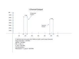
I Channel Output 0dB Unexpected Content -10dB -17dB -20dB -27dB -30dB -40dB Expected Content -50dB -60dB -70dB 813 748 293 228 130 260 390 520 650 780 910 • 2 identical real sine waves (32.5 MHz) on both I and Q input channels • Input Data Rate = 130 MHz • RefClk = 130 MHz • N1 = 2, N2 = 4 • F_Dac = 520 MHz • 4x Interpolation • Modulation = F_Dac/2 = 260 MHz
Q Channel Output 0dB Unexpected Content -10dB -20dB -30dB -30dB -40dB -42dB Expected Content -50dB -60dB -70dB 813 748 293 228 130 260 390 520 650 780 910 • 2 identical real sine waves (32.5 MHz) on both I and Q input channels • Input Data Rate = 130 MHz • RefClk = 130 MHz • N1 = 2, N2 = 4 • F_Dac = 520 MHz • 4x Interpolation • Modulation = F_Dac/2 = 260 MHz