Download
1 / 44
470 likes | 771 Views
Closed Conduit Hydraulics. CE154 - Hydraulic Design Lecture 6. Hydraulics of Closed Conduit Flow. Synonyms - closed conduit flow - pipe flow - pressurized flow Objectives – to introduce - basic concepts of closed conduit flow, - its hydraulics, and - design method. Concepts.

E N D
Closed Conduit Hydraulics CE154 - Hydraulic Design Lecture 6 CE154
Hydraulics of Closed Conduit Flow • Synonyms- closed conduit flow- pipe flow- pressurized flow • Objectives – to introduce- basic concepts of closed conduit flow, - its hydraulics, and - design method CE154
Concepts • Closed Conduit vs. Open Channel CE154
Concepts – Reynolds Number • Reynolds Number (ratio of inertia force to viscous force)V = velocity (ft/sec)D = pipe diameter (ft) = density of fluid (lbm/ft3) = dynamic viscosity of fluid (lbm/ftsec or lbfsec/ft2) = kinematic viscosity (ft2/sec) CE154
Concepts – Froude Number • Froud Number (ratio of inertia force to gravitational force) • V = velocityg = gravitational accelerationh = depth of water CE154
Concepts - Turbulence • Turbulent vs. laminar flow CE154
Concepts – turbulent flow • Turbulent flow - Critical Re (laminar to turbulent) in the order of 1000 CE154
Concepts – laminar flow • Turbulent and Laminar flows CE154
Concepts – uniform & steady flow • Uniform flow – constant characteristics with respect to space • Steady flow – constant characteristics with respect to time. Often adopted when establishing pipe system design parameters (pressure & flow at certain locations). Consider unsteady (transient) phenomena to refine design (pipe pressure class and thickness) CE154
Conservation of Mass 1 Control Volume 2 CE154
Conservation of Mass • Consider the control volume CE154
Conservation of Mass • For steady & incompressible flow, dS/dt = 0I = OV1A1 = V2A2 ViAi = VoAo CE154
Conservation of Mass • Apply to a pipe junction, Q1+Q2 = Q3+Q4 CE154
Conservation of Momentum • Newton’s 2nd law – the resultant of all external forces on a system is equal to the time rate of change of momentum of this system CE154
Conservation of Momentum • Consider this control volume (CV) of fluid in a pipe elbow x1=v1t 1 1’ 2 2’ x2=v2t CE154
Conservation of Momentum • In a time t the fluid originally at Section 1 moves to 1’, and that at Section 2 moves to 2’ • The control volume lost momentum equal to that of the fluid contained between 1 and 1’(A1x1)V1 = A1V12t = (QV1)tAt the same time it gained momentum (QV2)t CE154
Conservation of Momentum • The time rate of change of momentum is (QV2)- (QV1) • Hence, the 2nd Law becomes • This is the momentum equation for steady flow. Use this convention: • QVx1 Fx = QVx2 • QVy1 Fy = QVy2 • Where depends on the direction of the force w.r.t. the coordinate system CE154
Application of Momentum Eq. • Forces on a pipe elbow:Taking momentum balance in the x direction,QV1 + (PA)1 – Fx = Q(0)Fx = (PA)1 + QV1 CE154
Application of Momentum Eq. • Taking momentum balance in the y direction,External y force = (PA)2 - FyRate of change of momentum = QV2 (where V2 is in the negative direction) (PA)2 - Fy = QV2 Fy = (PA)2 - QV2 = (PA)2 + QV2 CE154
Conservation of Energy • In pipeline design, most often consider steady state – flow not varying with time - first • Steady state (SS) Bernoulli Equation along a streamline: CE154
Conservation of Energy • Pressure head p/ • Elevation head z • Velocity head V2/2g • Piezometric head p/ + z (hydraulic grade line) • Total head p/ + z + V2/2g (energy grade line) • Head Loss h CE154
Uniform Flow: CE154
Example 3-1 • A plane jet of unit discharge q0 strikes a boundary at an angle of 45, what will be the ratio of q1/q2 for the divided flow? CE154
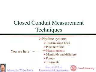
Head Losses • Include mostly 2 types of losses: • Friction Loss- resulting from friction between the fluid and pipe wall • Minor Loss- resulting from pipe entrance, transition, exit, valve and other in-line structures CE154
Friction Loss • Most useful head loss equation for closed-conduit flow – Darcy-Weisbach equation Pipe length Friction head loss Pipe velocity Dimensionless Friction coefficient Gravitational acceleration Pipe diameter CE154
Friction Loss • Darcy-Weisbach equation- derived from basic relationships of physics - dimensionless, app. to all unit systems- determined from experimental data • Other friction loss relationships – Hazen-Wiliams, Manning, Chezy, etc. – are also used in the industry, but are less accurate and will not be discussed here CE154
Darcy-Weisbach • Laminar flow (Re<2000)Turbulent flow in smooth pipes (Re>4000) CE154
Darcy-Weisbach (cont’d) • Turbulent flow in rough pipesTransition between turbulent smooth and rough pipes CE154
Friction Loss CE154
Darcy-Weisbach • Most recent development of Darcy Weisbach coefficient - Explicit equation [Swamee and Jain, 1976] applicable to entire turbulent flow regime (smooth, transition and rough pipes): CE154
Minor Loss • Use minor loss coefficient (k) in this form CE154
Minor Loss CE154
Minor Loss • For abrupt expansion, from D1 to D2, the loss coefficient may be estimated by CE154
Minor Loss • American Water Works Association – Steel Pipe, A guide for design and installation, Manual of Water Supply Practices, M11, 4th Edition, 2004 CE154
Minor Loss CE154
Minor Loss • Valve manufacturer has loss curves typically presented in terms of Cv vs. valve opening degrees. Cv is defined as the flow rate in gallons per minute of 60 water that flows through the valve under 1 psi of head loss. CE154
Globe Valve CE154
Angle Valve CE154
Example 3-2 • p. 2.24 of Mays’ Hydraulic Design Handbook – Calculate f and e/D from given discharge V2/2g=1.21 m Atmospheric Pressure P=3MPa L=2500 m El. 200 m D=27 in El. 100 m Q=1.8 cms CE154
Example 3-3 • Same problem but now we have an 20” in-line ball valve with a 20” bore opened at 70 from closed position, a contraction and expansion section each connected to the valve, and 2 90 elbows with r/D=2. What is the f now? CE154