
Ethernet Frame Structure
E N D
Presentation Transcript
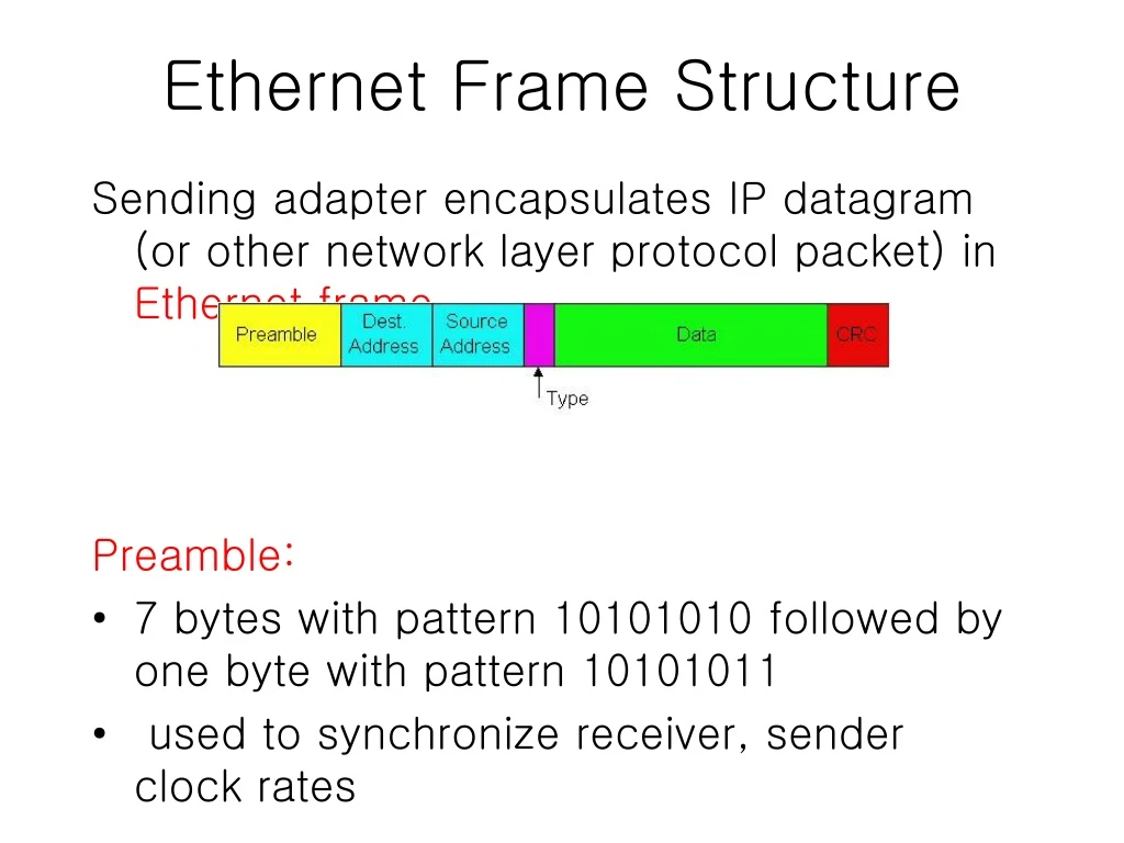
Ethernet Frame Structure Sending adapter encapsulates IP datagram (or other network layer protocol packet) in Ethernet frame Preamble: • 7 bytes with pattern 10101010 followed by one byte with pattern 10101011 • used to synchronize receiver, sender clock rates
Ethernet Frame Structure (more) • Addresses: 6 bytes • if adapter receives frame with matching destination address, or with broadcast address (eg ARP packet), it passes data in frame to net-layer protocol • otherwise, adapter discards frame • Type: indicates the higher layer protocol, mostly IP but others may be supported such as Novell IPX and AppleTalk) • CRC: checked at receiver, if error is detected, the frame is simply dropped
Unreliable, connectionless service • Connectionless: No handshaking between sending and receiving adapter. • Unreliable: receiving adapter doesn’t send acks or nacks to sending adapter • stream of datagrams passed to network layer can have gaps • gaps will be filled if app is using TCP • otherwise, app will see the gaps
No slots adapter doesn’t transmit if it senses that some other adapter is transmitting, that is, carrier sense transmitting adapter aborts when it senses that another adapter is transmitting, that is, collision detection Before attempting a retransmission, adapter waits a random time, that is, random access Ethernet uses CSMA/CD
1. Adaptor gets datagram from and creates frame 2. If adapter senses channel idle, it starts to transmit frame. If it senses channel busy, waits until channel idle and then transmits 3. If adapter transmits entire frame without detecting another transmission, the adapter is done with frame ! 4. If adapter detects another transmission while transmitting, aborts and sends jam signal 5. After aborting, adapter enters exponential backoff: after the mth collision, adapter chooses a K at random from {0,1,2,…,2m-1}. Adapter waits K*512 bit times and returns to Step 2 Ethernet CSMA/CD algorithm
Jam Signal: make sure all other transmitters are aware of collision; 48 bits; Bit time: .1 microsec for 10 Mbps Ethernet ;for K=1023, wait time is about 50 msec Exponential Backoff: Goal: adapt retransmission attempts to estimated current load heavy load: random wait will be longer first collision: choose K from {0,1}; delay is K x 512 bit transmission times after second collision: choose K from {0,1,2,3}… after ten collisions, choose K from {0,1,2,3,4,…,1023} Ethernet’s CSMA/CD (more) See/interact with Java applet on AWL Web site: highly recommended !
CSMA/CD efficiency • Tprop = max prop between 2 nodes in LAN • ttrans = time to transmit max-size frame • Efficiency goes to 1 as tprop goes to 0 • Goes to 1 as ttrans goes to infinity • Much better than ALOHA, but still decentralized, simple, and cheap
Ethernet Technologies: 10Base2 • 10: 10Mbps; 2: under 200 meters max cable length • thin coaxial cable in a bus topology • repeaters used to connect up to multiple segments • repeater repeats bits it hears on one interface to its other interfaces: physical layer device only! • has become a legacy technology
nodes hub 10BaseT and 100BaseT • 10/100 Mbps rate; latter called “fast ethernet” • T stands for Twisted Pair • Nodes connect to a hub: “star topology”; 100 m max distance between nodes and hub • Hubs are essentially physical-layer repeaters: • bits coming in one link go out all other links • no frame buffering • no CSMA/CD at hub: adapters detect collisions • provides net management functionality
Manchester encoding • Used in 10BaseT, 10Base2 • Each bit has a transition • Allows clocks in sending and receiving nodes to synchronize to each other • no need for a centralized, global clock among nodes! • Hey, this is physical-layer stuff!
Gbit Ethernet • use standard Ethernet frame format • allows for point-to-point links and shared broadcast channels • in shared mode, CSMA/CD is used; short distances between nodes to be efficient • uses hubs, called here “Buffered Distributors” • Full-Duplex at 1 Gbps for point-to-point links • 10 Gbps now !
5.1 Introduction and services 5.2 Error detection and correction 5.3Multiple access protocols 5.4 LAN addresses and ARP 5.5 Ethernet 5.6 Hubs, bridges, and switches 5.7 Wireless links and LANs 5.8 PPP 5.9 ATM 5.10 Frame Relay Chapter 5 outline
Multiple Access Links and Protocols Two types of “links”: • point-to-point • PPP for dial-up access • point-to-point link between Ethernet switch and host • broadcast (shared wire or medium) • traditional Ethernet • upstream HFC • 802.11 wireless LAN
Multiple Access protocols • single shared broadcast channel • two or more simultaneous transmissions by nodes: interference • only one node can send successfully at a time multiple access protocol • distributed algorithm that determines how nodes share channel, i.e., determine when node can transmit • communication about channel sharing must use channel itself! • what to look for in multiple access protocols:
Ideal Mulitple Access Protocol Broadcast channel of rate R bps 1. When one node wants to transmit, it can send at rate R. 2. When M nodes want to transmit, each can send at average rate R/M 3. Fully decentralized: • no special node to coordinate transmissions • no synchronization of clocks, slots 4. Simple
MAC Protocols: a taxonomy Three broad classes: • Channel Partitioning • divide channel into smaller “pieces” (time slots, frequency, code) • allocate piece to node for exclusive use • Random Access • channel not divided, allow collisions • “recover” from collisions • “Taking turns” • tightly coordinate shared access to avoid collisions
Channel Partitioning MAC protocols: TDMA TDMA: time division multiple access • access to channel in "rounds" • each station gets fixed length slot (length = pkt trans time) in each round • unused slots go idle • example: 6-station LAN, 1,3,4 have pkt, slots 2,5,6 idle • TDM (Time Division Multiplexing): channel divided into N time slots, one per user; inefficient with low duty cycle users and at light load. • FDM (Frequency Division Multiplexing): frequency subdivided.
Channel Partitioning MAC protocols: FDMA FDMA: frequency division multiple access • channel spectrum divided into frequency bands • each station assigned fixed frequency band • unused transmission time in frequency bands go idle • example: 6-station LAN, 1,3,4 have pkt, frequency bands 2,5,6 idle • TDM (Time Division Multiplexing): channel divided into N time slots, one per user; inefficient with low duty cycle users and at light load. • FDM (Frequency Division Multiplexing): frequency subdivided. time frequency bands
Channel Partitioning (CDMA) CDMA (Code Division Multiple Access) • unique “code” assigned to each user; i.e., code set partitioning • used mostly in wireless broadcast channels (cellular, satellite, etc) • all users share same frequency, but each user has own “chipping” sequence (i.e., code) to encode data • encoded signal = (original data) X (chipping sequence) • decoding: inner-product of encoded signal and chipping sequence • allows multiple users to “coexist” and transmit simultaneously with minimal interference (if codes are “orthogonal”)
Random Access Protocols • When node has packet to send • transmit at full channel data rate R. • no a priori coordination among nodes • two or more transmitting nodes -> “collision”, • random access MAC protocol specifies: • how to detect collisions • how to recover from collisions (e.g., via delayed retransmissions) • Examples of random access MAC protocols: • slotted ALOHA • ALOHA • CSMA, CSMA/CD, CSMA/CA
Assumptions all frames same size time is divided into equal size slots, time to transmit 1 frame nodes start to transmit frames only at beginning of slots nodes are synchronized if 2 or more nodes transmit in slot, all nodes detect collision Operation when node obtains fresh frame, it transmits in next slot no collision, node can send new frame in next slot if collision, node retransmits frame in each subsequent slot with prob. p until success Slotted ALOHA
Pros single active node can continuously transmit at full rate of channel highly decentralized: only slots in nodes need to be in sync simple Cons collisions, wasting slots idle slots nodes may be able to detect collision in less than time to transmit packet Slotted ALOHA
Suppose N nodes with many frames to send, each transmits in slot with probability p prob that 1st node has success in a slot = p(1-p)N-1 prob that any node has a success = Np(1-p)N-1 For max efficiency with N nodes, find p* that maximizes Np(1-p)N-1 For many nodes, take limit of Np*(1-p*)N-1 as N goes to infinity, gives 1/e = .37 Slotted Aloha efficiency Efficiency is the long-run fraction of successful slots when there’s many nodes, each with many frames to send At best: channel used for useful transmissions 37% of time!
Pure (unslotted) ALOHA • unslotted Aloha: simpler, no synchronization • when frame first arrives • transmit immediately • collision probability increases: • frame sent at t0 collides with other frames sent in [t0-1,t0+1]
Pure Aloha efficiency P(success by given node) = P(node transmits) . P(no other node transmits in [t0-1,t0] . P(no other node transmits in [t0,t0+1] = p . (1-p)N-1 . (1-p)N-1 = p . (1-p)2(N-1) … choosing optimum p and then letting n -> infty ... = 1/(2e) = .18 Even worse !
CSMA (Carrier Sense Multiple Access) CSMA: listen before transmit: • If channel sensed idle: transmit entire frame • If channel sensed busy, defer transmission • Human analogy: don’t interrupt others!
CSMA collisions spatial layout of nodes collisions can still occur: propagation delay means two nodes may not hear each other’s transmission collision: entire packet transmission time wasted note: role of distance & propagation delay in determining collision probability
CSMA/CD (Collision Detection) CSMA/CD: carrier sensing, deferral as in CSMA • collisions detected within short time • colliding transmissions aborted, reducing channel wastage • collision detection: • easy in wired LANs: measure signal strengths, compare transmitted, received signals • difficult in wireless LANs: receiver shut off while transmitting • human analogy: the polite conversationalist
5.1 Introduction and services 5.2 Error detection and correction 5.3Multiple access protocols 5.4 LAN addresses and ARP 5.5 Ethernet 5.6 Hubs, bridges, and switches 5.7 Wireless links and LANs 5.8 PPP 5.9 ATM 5.10 Frame Relay Chapter 5 outline
802.11b 2.4-5 GHz unlicensed radio spectrum up to 11 Mbps direct sequence spread spectrum (DSSS) in physical layer all hosts use same chipping code widely deployed, using base stations 802.11a 5-6 GHz range up to 54 Mbps 802.11g 2.4-5 GHz range up to 54 Mbps All use CSMA/CA for multiple access All have base-station and ad-hoc network versions IEEE 802.11 Wireless LAN
Base station approach • Wireless host communicates with a base station • base station = access point (AP) • Basic Service Set (BSS) (a.k.a. “cell”) contains: • wireless hosts • access point (AP): base station • BSSs combined to form distribution system (DS)
Ad Hoc Network approach • No AP (i.e., base station) • wireless hosts communicate with each other • to get packet from wireless host A to B may need to route through wireless hosts X,Y,Z • Applications: • “laptop” meeting in conference room, car • interconnection of “personal” devices • battlefield • IETF MANET (Mobile Ad hoc Networks) working group
IEEE 802.11: multiple access • Collision if 2 or more nodes transmit at same time • CSMA makes sense: • get all the bandwidth if you’re the only one transmitting • shouldn’t cause a collision if you sense another transmission • Collision detection doesn’t work: hidden terminal problem
IEEE 802.11 MAC Protocol: CSMA/CA 802.11 CSMA: sender - if sense channel idle for DISF sec. then transmit entire frame (no collision detection) -ifsense channel busy then binary backoff 802.11 CSMA receiver - if received OK return ACK after SIFS (ACK is needed due to hidden terminal problem)
Collision avoidance mechanisms • Problem: • two nodes, hidden from each other, transmit complete frames to base station • wasted bandwidth for long duration ! • Solution: • small reservation packets • nodes track reservation interval with internal “network allocation vector” (NAV)
Collision Avoidance: RTS-CTS exchange • sender transmits short RTS (request to send) packet: indicates duration of transmission • receiver replies with short CTS (clear to send) packet • notifying (possibly hidden) nodes • hidden nodes will not transmit for specified duration: NAV
Collision Avoidance: RTS-CTS exchange • RTS and CTS short: • collisions less likely, of shorter duration • end result similar to collision detection • IEEE 802.11 allows: • CSMA • CSMA/CA: reservations • polling from AP
Low-power, small radius, wireless networking technology 10-100 meters omnidirectional not line-of-sight infrared Interconnects gadgets 2.4-2.5 GHz unlicensed radio band up to 721 kbps Interference from wireless LANs, digital cordless phones, microwave ovens: frequency hopping helps MAC protocol supports: error correction ARQ Each node has a 12-bit address A word about Bluetooth