
CANopen
E N D
Presentation Transcript
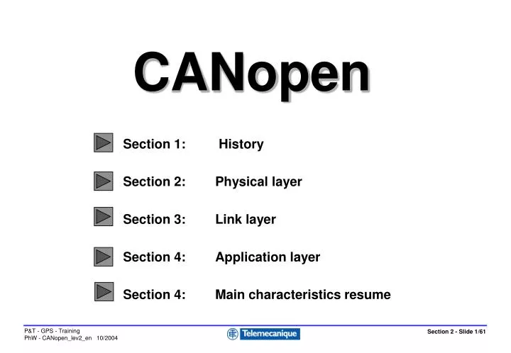
CANopen Section 1: History Section 2: Physical layer Section 3: Link layer Section 4: Application layer Section 4: Main characteristics resume
CANopen Section 1: History
Section 1 : History History • 1980-1983: • CAN developed on the initiative of the German equipment manufacturer BOSCH in response to a need in the automotive industry. • CAN defines only part of layers 1 and 2 of the ISO model. • 1983-1987: • Price of drivers and micro-controllers with integral CAN very attractive because of the high volume used by the automotive industry • 1991: • Launch of CiA = CAN in Automation: http://www.can-cia.de/ to promote industrial applications
Section 1 : History History • 1993: • Publication by CiA of CAL = CAN Application Layer specifications describing transmission mechanisms without defining when and how to use them. • 1995: • Publication by CiA of the DS-301communication profile: CANopen • 2001: • Publication by CiA of DS-304, enabling level 4 safety components to be integrated onto a standard CANopen bus (CANsafe).
CANopen was built chronologically on the basis of several specifications: CAN 2.0 A and B (originating from Robert BOSCH) Defines precisely the link layer and part of the physical layer CAL = CAN Application Layer (CiA): Provides tools for developing an application using CAN without instructions for use + further details on the physical layer CANopen (CiA): Defines which CAL tools to use and how. Ensures interoperability of products by profile descriptions. Section 1 : History Reference specifications
Section 1 : History CANopen and the ISO model Device Profile CiA DSP-401 I/O modules Device Profile CiA DSP-402 Drives Device Profile CiA DSP-404 Measuring devices Device Profile CiA DSP-4xx 7 APPLICATION CiA DS-301 = Communication profile CAL= CAN Application Layer 6 PRESENTATION EMPTY EMPTY 5 SESSION 4 TRANSPORT EMPTY 3 NETWORK EMPTY CAN 2.0 A and B + ISO 11898 2 LINK = LLC + MAC CAN specifications 1 PHYSICAL CAN 2.0 A and B = ISO 11898 ISO 11898 + DS-102
CANopen Section 2: Physical layer Part 1: Network characteristics Part 2: Recommended connections
Section 2: Physical layer - Part 1: Network characteristics CANopenphysical layer Device Profile CiA DSP-401 I/O modules Device Profile CiA DSP-402 Drives Device Profile CiA DSP-404 Measuring devices Device Profile CiA DSP-4xx 7 APPLICATION CiA DS-301 = Communication profile CAL= CAN Application Layer EMPTY 6 PRESENTATION EMPTY 5 SESSION EMPTY 4 TRANSPORT 3 NETWORK EMPTY CAN 2.0 A and B + ISO 11898 2 LINK = LLC + MAC CAN 2.0 A and B + ISO 11898 1 PHYSICAL ISO 11898 + DS-102 + DRP-301-1
Twisted differential pair: 1 pair if CAN-H/CAN-L 2 pairs if CAN-H/CAN-L + p. supply Characteristic line impedance: 120 ohms nominal Line terminators: 120 ohms at each end Wire resistance: 70 milli-ohms/metre nominal Propogation time: 5 ns/metre nominal Topology: Bus type with the shortest possible tap links Section 2: Physical layer - Part 1: Network characteristics Description of the network
Section 2: Physical layer - Part 1: Network characteristics Data rate - bus length - cable cross-section for 32 slaves maximum
Section 2: Physical layer - Part 1: Network characteristics Data rate - bus length - cable cross-section for 100 slaves maximum
In its recommendation DR-303-1, the CiA provides a list of suitable connectors classified into 3 categories. General use 9-pin SUB D connector DIN 41652, multi-pole connector (ribbon cable to 9-pin SUB-D), RJ10 and RJ45 Industrial use 5-pin Mini Style, 5-pin Micro Style, Open Style Special use 7-pin round connector, 8-pin round connector, 9-pin round connector, 12-pin round connector, Hand Brid Harting. Section 2: Physical layer - Part 2: Recommended connections Recommended connections
Pin Signal Description: 1: Reserved 2: CAN_L = CAN_L bus line dominant low 3: CAN_GND = CAN Ground 4: Reserved 5: (CAN_SHLD) Optional CAN Shield 6: (GND) Optional Ground 7: CAN_H = CAN_H bus line dominant high 8: Reserved 9: (CAN_V+) Optional CAN external positive supply Section 2: Physical layer - Part 2: Recommended connections 9-pin SUB D connector DIN 41652 Male product end
Pin Signal Description 1: CAN_H = CAN_H bus line (dominant high) 2: CAN_L = CAN_L bus line (dominant low) 3: CAN_GND = Ground/0 V/V- 4: Reserved 5: Reserved 6: (CAN_SHLD) = Optional CAN Shield 7: CAN_GND = Ground/0 V/V- 8 (CAN_V+) = Optional CAN external positive supply Section 2: Physical layer - Part 2: Recommended connections RJ45 connector
Pin Signal Description: 1: (CAN_SHLD) = Optional CAN Shield 2: (CAN_V+) = Optional CAN external positive supply 3: CAN_GND = Ground/0V/V- 4: CAN_H = CAN_H bus line (dominant high) 5: CAN_L = CAN_L bus line (dominant low) Section 2: Physical layer - Part 2: Recommended connections 5-pin Mini Style connector: ANSI/B93.55M-1981 Male product end
Pin Signal Description: 1: CAN_GND = Ground/0 V/V- 2: CAN_L = CAN_L bus line (dominant low) 3: (CAN_SHLD) = Optional CAN Shield 4: CAN_H = CAN_H bus line (dominant high) 5: (CAN_V+) = Optional CAN external positive supply Section 2: Physical layer - Part 2: Recommended connections Open Style connector Male product end
Cables - U.I.LAPP GmbH Schultze-Delitsch-Str. 25 D-70565 Stuttgart Germany http://www.lappcable.com Connectors - ERNI Elektroapparate GmbHSeestrasse 9 D-73099 Adelberg Germany - ERNI Connectique S.a.r.l, France 27 bis, avenue des Sources/CP 638 F-69258 LYON Cedex 09, http://connect.erni.com/ Section 2: Physical layer - Part 2: Recommended connections Recommended suppliers
CANopen Section 3: Link layer
The CAN V2.0 specification consists of 2 parts: CAN 2.0.A and CAN 2.0.B. CAN 2.0.A corresponds to the standardframe format with an identifier coded on 11 bits. It is used by CANopen and most of the application layers. CAN 2.0.B corresponds to the extendedframe format with an identifier coded on 29 bits. It is very rarely used. Section 3: Link layer CAN 2.0.A and CAN 2.0.B
Section 3: Link layer Structure of the CAN 2.0.A frame Arbitration field Frame size without bit stuffing: 47 to 111 bits 1 11 1 6 0 to 64 15 1 1 1 7 Data field CRC delimit. ACK delimit. RTR Remote Transmission Request bit Start of frame (SOF) CRC sequence ACK slot End of frame (EOF) Identifier Control field: compatibility and length
S2 S3 S1 Section 3: Link layer Dominant and recessive bits Identifier Controlfield SOF RTR 10 9 8 7 6 5 4 3 2 1 0 R Station 1 loses arbitration Station 1 D Station 2 Station 2 loses arbitration Station 3 Bus
Each node must always contain two counters: TEC Transmit Error Counter and REC Receive Error Counter. These counters are incremented and decremented using a sophisticated weighting mechanism etched in the silicon. Depending on the value of these counters, the node will be in one of the following 3 states: Active errors Passive errors Bus OFF (sending driver disconnected from the bus). Section 3: Link layer Error counters
Section 3: Link layer Counter value/node status Reset and configuration Active errors REC > 127or TEC > 127 REC < 128and TEC < 128 128 occurrences of 11 consecutive recessive bits (end of frames without errors) Passive errors TEC > 255 Bus OFF
Data Frame: these frames transport data from a producer to consumers without any guarantee that it will be processed. Remote Frame: these request frames are sent by a client to a server to request transmission of a data frame (the identifier will have the same value as that of the request). Error Frame: these frames are transmitted when a station detects the presence of errors on the bus. Overload Frame: these frames are sent to ask for an additional time lapse between successive frames (data or request). Section 3: Link layer The 4 types of CAN frame
If a request frame is repeated, the response to this request takes priority. Section 3: Link layer CAN V2.0 A Data Frame Data frame SOF IDENT RTR CTR DATA CRC ACK EOF Interframe 0 to 64X 1D 1D 11X 6X 5X+1R 1X+1R 7R 3R CAN V2.0 A Remote Frame Request frame SOF IDENT RTR CTR DATA CRC ACK EOF Interframe 0 to 64X 1D 3R 11X 6X 5X+1R 1X+1R 7R 1R
Section 3: Link layer Error Frame Error detected ERROR FLAG ERROR DELIMITER Frame being broadcast ACTIVE ERROR FLAG: 6D 8R PASSIVE ERROR FLAG: 6R Overload Frame EOF or ERROR DELIMITER OVERLOAD FLAG OVERLOAD DELIMITER Previous frame 6D 8R
At bit level: when 5 identical bits are transmitted, an additional "stuffing" bit with the opposite value is introduced intentionally. This bit is tested and eliminated by the receiver. At frame structure level, the delimiters CRC Delimiter, ACK Delimiter, End of Frame, Error Delimiter, Overload Delimiter are integrated to enable the structure to be checked. At content validity level: a CRC sequence enables receivers to check the consistency of the data received. ACK slot: this window enables the sender to know that his message has been received correctly by at least one station (dominant bit). Section 3: Link layer Protection mechanisms
CANopen Section 4: Application layer Part 1: CANopen basic concepts Part 2: CANopen objects and services
Section 4: Application layer - Part 1: CANopen basic concepts CANopen is based on CAL Device Profile CiA DSP-401 I/O modules Device Profile CiA DSP-402 Drives Device Profile CiA DSP-404 Measuring devices Device Profile CiA DSP-4xx 7 APPLICATION CiA DS-301 = Communication profile CAL= CAN Application Layer 6 PRESENTATION EMPTY EMPTY 5 SESSION 4 TRANSPORT EMPTY 3 NETWORK EMPTY CAN 2.0 A and B + ISO 11898 2 LINK = LLC + MAC 1 PHYSICAL CAN 2.0 A and B = ISO 11898-1 and 2 ISO 11898 + DS-102
CANopen defines: how data is transmitted: DS-301 communication profile common to all products Amongst other things this defines the allocation of COB-ID identifiers for each type of message. what data is transmitted: DS-4xx product profiles specific to each product family (discrete I/O, analogue I/O, variable speed drives, encoders, etc.) These functions are described by means of a Device Object Dictionary (OD). Section 4: Application layer - Part 1: CANopen basic concepts Application layer
The object dictionary OD is a sequenced group of objects that can be accessed by means of: a 16-bit index and in some cases an 8-bit sub-index It describes all the functions of the product. This description takes the form of an EDS file (Electronic Data Sheet) in ASCII format. This has a strict syntax and can be used by the bus configurators (Sycon etc.) Section 4: Application layer - Part 1: CANopen basic concepts Object Dictionary = OD
Section 4: Application layer - Part 1: CANopen basic concepts Structure of the “Object Dictionary”
The DS-301 communication profile: Describes the general structure of the OD and the objects located in the communication profile area: index 1000 to 1FFF. It applies to all CANopen products. DS-4xx equipment profiles: Describe associated objects for the various types of product (discrete I/O modules, analogue I/O, variable speed drives, measuring instruments). Standardised objects: index 6000 to 9FFF Specific objects: index 2000 to 5FFF Some objects are mandatory, others are optional. They can be accessed in read-only mode or in read/write mode. Section 4: Application layer - Part 1: CANopen basic concepts CANopen profiles
Section 4: Application layer - Part 1: CANopen basic concepts CANopen ATV58 EDS file extract • [FileInfo] • FileName=A58_F.eds • FileVersion=1 • FileRevision=2 • Description=Carte Option ATV58 • CreationTime=00:00AM • CreationDate=12-05-2000 • CreatedBy=Marie-Annick Menanteau, Schneider Electric • [DeviceInfo] • VendorName=Schneider Electric • ProductName=ATV58_F • ProductVersion=1 • ProductRevision=1 • BaudRate_10=0 • BaudRate_20=0 • BaudRate_50=0 • BaudRate_100=0 • BaudRate_125=1 • BaudRate_250=1 • BaudRate_500=1 • BaudRate_800=0 • BaudRate_1000=1 • Granularity=0x8 • VendorNumber=0x0200005a • ProductNumber=0 • SimpleBootUpMaster=0 • ExtendedBootUpMaster=0 • SimpleBootUpSlave=1 • ExtendedBootupSlave=0…. • [Comments] • Lines=6 • Line1=Used profile: 402 • Line2=Manufacturer device name: VW3A58306 • Line3=Hardware version: 1.0 • Line4=Software version: 1.0 • Line6= This is the EDS file for the CANopen Schneider Electric ATV58 drive module CAN Communication Adapter • [MandatoryObjects] • SupportedObjects=12 • 1=0x1000 • 2=0x1001 • 3=0x6040 • 4=0x6041 • 5=0x6042 • 6=0x6043 • 7=0x6044 • 8=0x6046 • 9=0x6048 • 10=0x6049 • 11=0x6060 • 12=0x6061 • [1000] • ParameterName=Device Type • ObjectType=7 • DataType=0x0007 • AccessType=RO • DefaultValue=0x10192 • PDOMapping=0
The CANopen communication profile defines 4 standardised functions: 1 . Network administration: starting the bus, assigning identifiers, parameter setting and NMT (Network ManagemenT) monitoring (master-slave model) 2 . High-speed transmission of process data (<= 8 bytes): PDO = Process Data Object (producer-consumer model) 3 . - Transmission of parameter setting data (with segmentation can be > 8 bytes) (not time-critical): SDO = Service Data Object (client-server model) 4 . Predefined messages for managing synchronisation, time references, fatal errors: SFO = Special Function Object Section 4: Application layer - Part 1: CANopen basic concepts CANopen communication profile DS-301
Transitions performed by the NMT master:Types of communication objects authorised: 1: Start_Remote_Node a. NMT 2: Stop_Remote_Node b. Node Guard 3: Enter_Pre-Operational_State c. SDO 4: Reset_Node d. EMCY 5: Reset_Communication e. PDO. 6: Node initialisation stopped Section 4: Application layer - Part 2: CANopen objects and services Network management: NMT Starting the bus • Status chart corresponding to “CANopen minimum boot-up”* • (mandatory service)
Identifiers can be allocated in 3 different ways: Using the default allocation: CANopen Predefined Set This default allocation is compulsory and is available in the Pre-Operational state. It reduces the network configuration phase Process data is exchanged between the bus manager and the slaves Defined only for the first 4 PDOs : PDO1 to PDO4 By the user in the configuration tool : Mandatory for PDOs superior to PDO4, or PDO linking (direct exchanges between slaves) By application Pre-Operational state: Written into the objects in accordance with the dictionary by the SDO service Section 4: Application layer - Part 2: CANopen objects and services Allocation of identifiers
With the aim of reducing the network configuration phase a compulsory system for allocating default identifiers has been defined. This allocation occurs in the "Pre operational" state just after the initialization phase. It is based on dividing the COB-ID identifier into 2 parts: Function code is used to code 2 PDOs in receive mode, 2 PDOs in transmit mode, 1 SDO, 1 EMCY object, 1 Node Guarding Identifier, 1 SYNC object, 1 Time Stamp object and 1 node guarding. Node ID corresponds to the product address coded by DIP switches, for example. Section 4: Application layer - Part 2: CANopen objects and services Allocation of default identifiers 10 9 8 7 6 5 4 3 2 1 0 Function Code Node ID
Section 4: Application layer - Part 2: CANopen objects and services Allocation of default identifiers Allocation of default identifiers can be used on products which support the first 4 PDOs. (The fifth PDO overlaps the area reserved for SDO) 1024 identifiers maximum reserved for PDOs.
Section 4: Application layer - Part 2: CANopen objects and services Allocation of default identifiers Slave 1 Master Inputs Slave 2 All the nodes (slaves) communicate with a central station (master) Outputs Slave 3
Section 4: Application layer - Part 2: CANopen objects and services Modification of the default identifier allocation Product X Allows data to be exchanged directly without passing through the master (PDO linking). The producer-consumer concept is used. Example: Axis control Product Z Product Y
These services are used to transmit small amounts of process data (<= 8 bytes) in real time. They enable a producer device to make a variable with a maximum size of 64 bits without overheadavailabletoone or more consumers. This service is not confirmed PDO configuration is managed at the level of each slave There are 2 types of PDOs : Receive PDO : PDO received on slave side, output data for the master Transmit PDO : PDO sent by the slave, input data for the master Section 4: Application layer - Part 2: CANopen objects and services Process Data Objects = PDO
Each transmit or receive PDO is described by 2 objects in the object dictionary: The PDO Communication Parameter indicates how the PDO is transmitted or received: The COB-ID used The transmit/receive mode used For transmit PDOs, the minimum time between 2 messages (inhibit time) Receive PDO : Index 1400 to 15FF - Transmit PDO : Index 1800 to 19FF The PDO Mapping Parameter indicates what data is transmitted: The list of objects in the object dictionary OD The size of each object Receive PDO : Index 1600 to 17FF - Transmit PDO : Index 1A00 to 1BFF Section 4: Application layer - Part 2: CANopen objects and services Description of PDOs
Section 4: Application layer - Part 2: CANopen objects and services TxPDO communication parameter objects Transmit PDO: Index 0x1800 to 0x19FF
Section 4: Application layer - Part 2: CANopen objects and services TxPDO mapping parameter objects Transmit PDO: Index 0x1A00 to 0x1BFF
Section 4: Application layer - Part 2: CANopen objects and services RxPDO communication parameter objects Receive PDO: Index 0x1400 to 0x15FF
Section 4: Application layer - Part 2: CANopen objects and services RxPDO mapping parameter objects Receive PDO: Index 0x1600 to 0x17FF
Synchronous: by receiving a SYNC object Acyclic: - transmission is pre-triggered by a "Remote Transmission request" - transmission is pre-triggered by the occurrence of a "Specific event" object in the device profile Cyclic: - transmission is triggered periodically after each 1, 2 or up to 240 SYNC objects Section 4: Application layer - Part 2: CANopen objects and services PDO transmission modes • Asynchronous: • - transmission is triggered by a "Remote Transmission request" - transmission is pre-triggered by the occurrence of a "Specific event" object in the device profile
These services are used for the point to point transmission of parameter setting data which is not time critical. They enable a client device (bus manager) to access the object dictionary of a server device (stations 1 to 127) in write or read mode, by addressing it by its Index and Sub-index. The size of the data may exceed 8 bytes, in which case a data segmentation system is activated. The result of a write or read operation is confirmed by a response. An SDO exchange requires 2 COB-IDs: one for the request, the other for the response. Section 4: Application layer - Part 2: CANopen objects and services Service Data Objects = SDO
SYNC = Synchronization Object: These objects are used to synchronize the acquisition of inputs or updating of outputs (axis control for example). The "SYNC master" sends the SYNC message at a an interval (communication cycle period) fixed at the time of configuration. Section 4: Application layer - Part 2: CANopen objects and services Special Function Objects = SFO