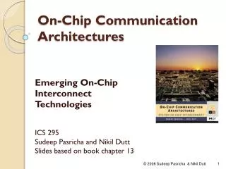
On - Chip Communication Architectures
On - Chip Communication Architectures. Emerging On-Chip Interconnect Technologies ICS 295 Sudeep Pasricha and Nikil Dutt Slides based on book chapter 13. Outline. Introduction Optical Interconnects RF/Wireless Interconnects CNT Interconnects Conclusion. Introduction.

On - Chip Communication Architectures
E N D
Presentation Transcript
On-Chip Communication Architectures Emerging On-Chip Interconnect Technologies ICS 295 Sudeep Pasricha and NikilDutt Slides based on book chapter 13 © 2008 Sudeep Pasricha & Nikil Dutt
Outline • Introduction • Optical Interconnects • RF/Wireless Interconnects • CNT Interconnects • Conclusion © 2008 Sudeep Pasricha & Nikil Dutt
Introduction • Modern on-chip electrical interconnects (EIs) are realized using copper wires • On-chip EIs can be classified into two categories • local interconnects: used for short distance communication and have a delay of less than a clock cycle • global interconnects: which are fewer in number, used for long distance communication and have a delay spanning multiple cycles • Long global EIs typically have high RC constants • which results in greater propagation delay, transition time, and crosstalk noise • Repeater insertion and increasing wire width can reduce the propagation delay somewhat • delay is still quite large in DSM technologies © 2008 Sudeep Pasricha & Nikil Dutt
Introduction • In DSM technologies, it is becoming increasingly harder for a copper-based electrical interconnect (EI) to satisfy design requirements • delay, power, bandwidth, delay uncertainty • Resistance of copper interconnects, in current and imminent technologies is increasing rapidly due to • enhanced grain boundary scattering • surface scattering • presence of a highly resistive diffusion barrier layer • Steep rise in parasitic resistance and capacitance of copper interconnects poses serious challenges for • interconnect delay (especially at the global level) • power dissipation • interconnect reliability © 2008 Sudeep Pasricha & Nikil Dutt
Introduction • Copper interconnects also constitute up to 70% of total on-chip capacitance • major sources of power dissipation • According to the International Technology Roadmap for Semiconductors (ITRS), interconnect innovation with new technologies is vital • to satisfy performance, reliability, power requirements in long term • support ultra-high data rates (greater than 100 Gbps/pin) • be scalable enough to support tens to hundreds of concurrent communication streams © 2008 Sudeep Pasricha & Nikil Dutt
Outline • Introduction • Optical Interconnects • RF/Wireless Interconnects • CNT Interconnects • Conclusion © 2008 Sudeep Pasricha & Nikil Dutt
Optical Interconnects • Optical interconnects (OIs) have potential to overcome communication bottleneck by replacing electrical wires with optical waveguides • OIs offer many advantages over traditional electrical (copper-based) interconnects • can support enormous intrinsic data bandwidths in the order of several Gbps using only simple on–off modulation schemes • relatively immune to electrical interference due to crosstalk, and parasitic capacitances and inductances • power dissipation is completely independent of transmission distance at the chip level • routing and placement is simplified since it is possible to physically intersect light beams with minimal crosstalk. • once a path is acquired, transmission latency of the optical data is very small, depending only on the group velocity of light in the waveguide © 2008 Sudeep Pasricha & Nikil Dutt
Optical Interconnects • While board-to-board and chip-to-chip OIs have been proposed and are actively under development, feasibility of on-chip OIs is an open research problem • High speed, electrically driven, on-chip monolithic light source still remains to be realized © 2008 Sudeep Pasricha & Nikil Dutt
Optical Interconnects • (Off-chip) laser source • provides light to modulator • Transmitter • electro-optical modulator • transduces electrical data supplied from electrical driver into a modulated optical signal • several high speed electro-optical modulators have been proposed • that change refractive index or absorption coefficient of an optical path when an electrical signal is injected • Mach-Zehnder interferometer-based silicon modulators • higher modulation speeds (several GHz) • large power consumption • greater silicon footprint (around 10 mm) • Microresonator-based P-I-N diode type modulators • compact in size (10–30 mm) • low power consumption • low modulation speeds (several MHz) © 2008 Sudeep Pasricha & Nikil Dutt
Optical Interconnects • Transmitter • modulator driver • consists of a series of inverter stages that drive the modulator ’s capacitive load © 2008 Sudeep Pasricha & Nikil Dutt
Optical Interconnects • Waveguide • path through which light is routed • refractive index of waveguide material has a significant impact on bandwidth, latency, and area of an OI • two promising alternatives for waveguide material that trade-off propagation speed and bandwidth • Silicon (Si) • lower propagation speed, but low area footprint (higher bandwidth density) • Polymer • higher propagation speed but greater area (reduced bandwidth density) © 2008 Sudeep Pasricha & Nikil Dutt
Optical Interconnects • Receiver • responsible for converting the optical signal back to an electrical signal • photo-detector • must have high value for quantum efficiency • lower losses when converting optical information into an electrical form • e.g. interdigitated metal–semiconductor–metal (MSM) receivers • fast response and excellent quantum efficiency • wave selective filter • optional – only used when(WDM) is used • selects among different wavelengths • trans-impedance amplifier (TIA) stage • converts photo-detector current to a voltage which is thresholded by subsequent stages to digital levels © 2008 Sudeep Pasricha & Nikil Dutt
Optical Interconnects • OIs possess an intrinsic advantage of low signal propagation delay in waveguides • due to the absence of RLC impedances © 2008 Sudeep Pasricha & Nikil Dutt
Optical Interconnects • OIs require an electrical signal to be first converted into an optical signal and then back into an electrical signal • conversion delay independent of interconnect length • OIs will have a delay advantage over EIs only if waveguide propagation delay dominates overall delay © 2008 Sudeep Pasricha & Nikil Dutt
Optical Interconnects • Minimum pitch between two adjacent waveguides is determined by crosstalk considerations • for a fixed pitch, if waveguide is too wide, then crosstalk is high due to proximity between sides of adjacent waveguides • If waveguide is too narrow, optical mode becomes less confined, causing a higher crosstalk due to larger overlap between adjacent optical modes © 2008 Sudeep Pasricha & Nikil Dutt
Optical Interconnects • Trade-off between waveguide density and propagation delay per unit length for a 10 mm interconnect and a maximum allowed crosstalk of 20% © 2008 Sudeep Pasricha & Nikil Dutt
Optical Interconnects • Comparison of projected bandwidth density for delay-optimize EIs and optical waveguides • optical bandwidth density increases due solely to the higher bit rate through waveguides with a fixed pitch • EIs exploit more efficient repeaters – leads to higher growth in bandwidth density © 2008 Sudeep Pasricha & Nikil Dutt
Optical Interconnects • Single wavelength OI is inferior to a delay-optimized EI in terms of bandwidth density • Why would anyone use OIs? • Wavelength division multiplexing (WDM) can improve bandwidth density for OIs over EIs © 2008 Sudeep Pasricha & Nikil Dutt
Optical Interconnects: Research • A few research efforts have studied how on-chip optical networks can be used for clock-tree networks • can reduce clock distribution skew on chip in multi-GHz range • Intel researchers have claimed that WDM can enable optics to achieve high bandwidth, low latency for global signaling • but this requires efficient high speed, low capacitance CMOS-compatible modulators, detectors, and practical WDM schemes • Chen et al. [TED 2004] argued that there is no significant skew and power advantages in using an optical solution • as most of skew, power of clk signaling arises in local clk distribution • Ackland et al. [CICC 2005] showed that an optical clock tree scales better than an H-tree electrical clock network • best solution might be a hybrid tree network, with optical front end and backend with small electrical trees © 2008 Sudeep Pasricha & Nikil Dutt
Optical Interconnects: Research • A few recent works have proposed using optical links in an on-chip network-on-chip (ONoC) • O’Connor [SLIP 2004] and Briere et al. [RSP 2005] gave a high level overview of a 4x4 2D mesh based optical NoC • Shacham et al. [DAC 2007] described a 2-D folded torus optical NoC • can theoretically result in high bandwidth, low power intra-chip comm. • Kirman et al. [MICRO 2006] proposed an optical loop network • Si waveguide on dedicated layer • support for WDM to improve bandwidth density • However ONoCs have a few drawbacks • high power overhead of electrical routers and opto-electric/electro-optic conversion at the interface of each component • lack of availability of wideband photonic switching elements © 2008 Sudeep Pasricha & Nikil Dutt
Optical Interconnects: Research • Recently, Pasricha et al. [ASPDAC 2008] proposed the ORB (optical ring bus) on-chip communication architecture • novel opto-electric communication architecture that uses an ORB as a global interconnect between computation clusters • preserves standard protocol interface (e.g., AMBA AXI) for inter- and intra-cluster communication • hybrid Mach-Zehnder interferometer/microresonator-based P-I-N diode modulators • ring-shaped low refractive index polymer waveguide • support for WDM • shown to dissipate significantly lower power (more than a 10x less) and improve overall performance (more than 2x) • compared to traditional pipelined, all-electrical global interconnects, across the 65–22 nm CMOS technology nodes © 2008 Sudeep Pasricha & Nikil Dutt
Optical Interconnects: Open Problems • Efficient transmitter and receiver components • high speed, low power, and small feature-size electro-optical modulators and photo-detector receivers need to be developed • Integrated on-chip light source • such as the Indium Phosphide Hybrid Silicon Laser from Intel and UCSB [2008] • Polymer waveguide • prohibitive manufacturing cost and complexity • require suitable modulators • Temperature management • OIs sensitive to temperature variations • active or passive optical control method required to maintain stable device operation © 2008 Sudeep Pasricha & Nikil Dutt
Outline • Introduction • Optical Interconnects • RF/Wireless Interconnects • CNT Interconnects • Conclusion © 2008 Sudeep Pasricha & Nikil Dutt
RF/Wireless Interconnects • Replace on-chip wires with integrated on-chip antennas communicating via electromagnetic waves • Data is converted from baseband (i.e., digital) to RF/microwave signals and transmitted through free space or guided mediums • Free space signal broadcasting and reception is a common practice in modern wireless systems • due to low cost implementation and excellent channeling capabilities • However, free space transmission and reception of RF/microwave signals requires an antenna size that is comparable to its wavelength • even at near 100 GHz operating and cut-off frequencies in the future the aperture size of the antenna = 1 mm2 which is too large © 2008 Sudeep Pasricha & Nikil Dutt
RF/Wireless Interconnects • Microwave transmission in guided mediums such as microstrip transmission line (MTL) or coplanar waveguide (CPW) is a more viable alternative to free space • low attenuation up to at least 200 GHz • requires a smaller antenna size • Simulation results have shown that a 1cm long CPW experiences extremely low loss (1.6 dB at 100 GHz), and low dispersion (less than 2 dB for 50–150 GHz) • EIs have 60 and 115 dB loss per cm at 100 GHz, and a freq dispersion of 30–40 dB • Thus microwave transmission over MTL or CPW has a clear advantage over conventional EIs • especially for global interconnects operating in multi-GHz range © 2008 Sudeep Pasricha & Nikil Dutt
RF/Wireless Interconnects • RF/wireless interconnect • multiple transmitters receivers • capacitive couplers as near-field antennas • RF circuits for transceivers • uniform and homogeneous MTL or CPW channel as a shared bidirectional broadcasting medium © 2008 Sudeep Pasricha & Nikil Dutt
RF/Wireless Interconnects • Simultaneous communications in RF/wireless interconnects possible using frequency division multiple access (FDMA) • RF modulated frequency bands can improve data bandwidth by transmitting data over multiple frequency bands • frequency bands of I/O channels can be allocated between 5–105 GHz with a bandwidth of approximately 5–40 Gbps in each channel • EIs only occupy lowest frequency band (baseband) © 2008 Sudeep Pasricha & Nikil Dutt
RF/Wireless Interconnects • Balanced or double balanced active mixers, such as the Gilbert cell, may be used for modulation and demodulation • Low loss and high selective BPFs needed in FDMA interconnects require tunable and high Q inductors • which are hard to realize due to their high energy loss to the conductive silicon substrate • can be partially resolved by using a transformer type inductor design • where lost energy is recovered via a secondary inductor with delayed phase angles to attain high inductance and tunability • Recent progress in MEMS (microelectromechanical systems) has shown promise for high Q silicon resonators and filters • in micrometer wave frequencies © 2008 Sudeep Pasricha & Nikil Dutt
RF/Wireless Interconnects • Simultaneous communications in RF/wireless interconnects possible using code division multiple access (CDMA) • data stream from a transmitter is first converted into a spread spectrum signal by orthogonal Walsh codes (or PN codes) • subsequently modulated with RF sinusoidal carrier • resulting signal from transmitters are capacitively coupled into a superposed multilevel signal on the shared CPW (or MTL) © 2008 Sudeep Pasricha & Nikil Dutt
RF/Wireless Interconnects • Unlike hardware-oriented FDMA interconnect, the CDMA interconnect can be easily reconfigured by changing spreading codes through software commands © 2008 Sudeep Pasricha & Nikil Dutt
RF/Wireless Interconnects • On-chip antennas fabricated on substrates are categorized as printed antennas • microstrip, dipole, and loop antennas linear meander zig-zag folded • Combining different antenna structures such as folded and meander can provide a higher power gain and a more compact on-chip antenna structure © 2008 Sudeep Pasricha & Nikil Dutt
RF/Wireless Interconnects • Some recent research has focused on using on-chip silicon substrate/dielectric layer as a transmission path • instead of using off-chip and in-package CPW or MTL guided mediums • At 24 GHz, wavelength of EM waves in silicon is 3.7 mm • a quarter wave antenna needs to be only about 0.9 mm in silicon • in conjunction with increased chip sizes of 2 cm x 2 cm, has made the integration of antennas for wireless on-chip communication feasible © 2008 Sudeep Pasricha & Nikil Dutt
RF/Wireless Interconnects • Paths formed by • passage through air • refraction through the SiO2 layer and reflection at the interface between the silicon substrate and the underlying dielectric layer (A1N) • refraction through the SiO2 and dielectric layers, and reflection by the metal chuck that emulates a heat sink in the back of a die © 2008 Sudeep Pasricha & Nikil Dutt
RF/Wireless Interconnects • Signals propagating on these multiple paths constructively and destructively interfere • It was found by O et al. [ICCAD 2005] that by increasing the AIN thickness, destructive signal interference is significantly reduced • Benech et al. [IECON 2006] conducted a similar feasibility study and found that • higher resistivity substrates are better suited for wireless communication • showed that antennas on lower resistivity silicon substrate present gains of 30 dB • in contrast, antennas on SOI (silicon on insulator) substrates of higher resistivity present gains of 15 dB • at frequencies around 30 GHz © 2008 Sudeep Pasricha & Nikil Dutt
RF/Wireless Interconnects: Research • Wireless interconnects may not only reduce the wires in integrated circuits, but can also be used to replace I/O pins • O et al. [GMAC 1999] proposed RF/wireless interconnects for clock networks to reduce signal skew • Test chips have been created to demonstrate the feasibility of RF/wireless on-chip interconnects and their use in clock networks • Guo et al. [SVLSI 2002] showed that a 15 GHz transmitted signal 2.2 cm away from a clock receiver with an on-chip antenna was successfully picked up by receiver and used to generate digital output • Floyd et al. [ISSCC 2000] presented another wireless clock implementation at 7.4 GHz frequency • Transmitting and receiving antenna placed 3.3 mm from each other © 2008 Sudeep Pasricha & Nikil Dutt
RF/Wireless Interconnects: Open Problems • Packaging and interference issues • metal structures near antennas can change input impedances and phase of received signals • interference effects between the transmitted/received signal and switching noise of nearby circuits • Ultra-high frequency requirements • for antenna sizes to be feasible for on-chip fabrication, RF circuits must operate in the ultra-high frequency domain (i.e., ~100 GHz range) • unsuitable for applications in the very near future • may be feasible by 2015 if scaling trends continue • Power overhead • each transceiver has its own dedicated RF and CDR circuits • heavy circuit overhead as well as large power consumption © 2008 Sudeep Pasricha & Nikil Dutt
RF/Wireless Interconnects: Open Problems • On-chip antennas • lot of research on fabricating antennas on lossless or lower loss substrates such as polytetrafluoroethylene (PTFE), quartz, duroid, and GaAs in the millimeter wave range • not been sufficient research in the area of fabricating printed antennas on silicon substrate • much more lossy than other types of substrates • reduces the antenna efficiency, requiring possibly greater power • Reference crystal oscillator • required for FDMA • cannot be easily implemented on-chip - has a large size • Security • RF/wireless interconnects may be susceptible to hackers © 2008 Sudeep Pasricha & Nikil Dutt
Outline • Introduction • Optical Interconnects • RF/Wireless Interconnects • CNT Interconnects • Conclusion © 2008 Sudeep Pasricha & Nikil Dutt
CNT Interconnects • Carbon nanotubes are CNTs are sheets of graphite rolled into cylinders of diameters varying from 0.6 to about 3 nm • Demonstrate either metallic or semiconducting properties • depending on direction in which they are rolled (chirality) • CNTs are promising candidates as on-chip interconnects • high mechanical and thermal stability • high thermal conductivity • large current carrying capacity • highly resistant to electromigration and other sources of breakdown • much better conductivity properties than Cu • due to longer electron mean free path (MFP) lengths in the micrometer range, compared to nanometer range MFP lengths for Cu © 2008 Sudeep Pasricha & Nikil Dutt
CNT Interconnects • It is predicted that isolated CNTs can replace Cu at the local interconnect level • because of their much lower lateral capacitance which improves latency for very short distances • However, for longer on-chip interconnections a bundle of CNTs conducting current in parallel are more suitable • because of high intrinsic resistance of an isolated CNT (> 6.45 KΩ) • A bundle of CNTs consists of • metallic nanotubes that contribute to current conduction, and • semiconducting nanotubes that do not contribute to current conduction in an interconnect • CNTs broadly classified into • SWCNT: isolated (single walled) CNT • MWCNT: multi-walled CNT, made up of concentric SWCNTS © 2008 Sudeep Pasricha & Nikil Dutt
Circuit Parameters for SWCNT • Resistance • fundamental resistance RF = h/4e2 = 6.45kΩfor lengths less than MFP • MFP (L0) is of electrons is distance across which no scattering occurs • for SWCNTS, practical value of MFP is about 1µm • for lengths less than L0, the resistance of a SWCNT is independent of length • for lengths larger than L0, resistance increases with length, and this can be expressed as RSWCNT = RF . (L/L0) • An additional source of resistance in SWCNTs is due to presence of imperfect metal-nanotube contacts • total resistance for SWCNTs (sum of fundamental, scattering and contact) can be extremely high for longer interconnect lengths • therefore isolated SWCNTs more suitable as local interconnects © 2008 Sudeep Pasricha & Nikil Dutt
Circuit Parameters for SWCNT • Capacitance • electrostatic capacitance • d = SWCNT diameter • y = distance from ground plane • y > 2d • quantum capacitance • h = Planck’s constant • vF = Fermi velocity • SWCNT has four conducting channels • the effective quantum capacitance due to four parallel capacitances is 4CQ © 2008 Sudeep Pasricha & Nikil Dutt
Circuit Parameters for SWCNT • Inductance • magnetic inductance • kinetic inductance • four parallel conducting channels in a CNT give rise to an effective kinetic inductance of LK/4 • typically, LK >> LM © 2008 Sudeep Pasricha & Nikil Dutt
Circuit Parameters for SWCNT Bundle • SWCNT bundles have lower resistance than SWCNTs • In a bundle, each SWCNT is surrounded by six immediate neighbors, with their centers separated by a distance x • densely packed bundle with x = d is desirable • in reality, not all SWCNTs of a bundle are metallic • there are non-metallic SWCNTs that do not contribute to current conduction • their presence is taken into account by considering a “sparsely” populated SWCNT bundle model, where x > d • metallic density (Pm) of an SWCNT bundle refers to the probability that an SWCNT in the bundle is metallic (Pm ≈ 1/3 today) © 2008 Sudeep Pasricha & Nikil Dutt
Circuit Parameters for SWCNT Bundle • Resistance • Capacitance • electrostatic capacitance arises mainly from SWCNTs lying at edges of bundle that are capacitively coupled with adjacent interconnects (left and right neighbors) as well as the substrate • Inductance © 2008 Sudeep Pasricha & Nikil Dutt
Comparison between Copper and SWCNT-Bundles • Resistance and capacitance of Cu and CNT bundle interconnects for local interconnect lengths © 2008 Sudeep Pasricha & Nikil Dutt
Comparison between Copper and SWCNT-Bundles • Propagation delay for local interconnects (dense bundle) • delay for densely packed CNT bundles is higher than that with Cu interconnects across all technology generations • even if contacts are perfect and an MFP as large as 10 µm is achieved • higher capacitance of dense CNT bundles and high resistance of minimum sized drivers at the local interconnect level overshadow advantage from low CNT bundle resistance © 2008 Sudeep Pasricha & Nikil Dutt
Comparison between Copper and SWCNT-Bundles • Propagation delay for local interconnects (sparse bundle) • performance of CNT bundles with perfect contacts becomes better than Cu wires if the distance between adjacent metallic CNTs forming a bundle is increased (i.e., sparser) • however, with realistic (i.e., imperfect) contacts, delay is still higher than Cu interconnects © 2008 Sudeep Pasricha & Nikil Dutt
Comparison between Copper and SWCNT-Bundles • Propagation delay for local-intermediate length interconnects • beyond a certain minimum length, performance of dense CNT bundle interconnects at this level is better than Cu wires • with technology scaling, this minimum length decreases while the improvement in performance increases © 2008 Sudeep Pasricha & Nikil Dutt
Comparison between Copper and SWCNT-Bundles • Propagation delay for global interconnects • global interconnects implemented with dense CNT bundles can achieve significantly better performance than copper • however this performance improvement depends on CNT MFP © 2008 Sudeep Pasricha & Nikil Dutt