Download
1 / 38
550 likes | 856 Views
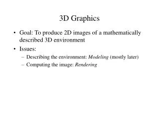
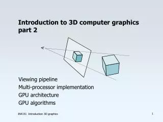
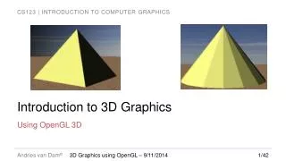
Introduction to 3D Graphics. Using OpenGL 3D. Classical Graphics Pipeline. Mesh objects with 3D polygons (triangles or quads usually) Apply material properties to each object Texture map polygons as needed Light scene Place camera Enjoy the view. Why OpenGL for 3D?.

E N D
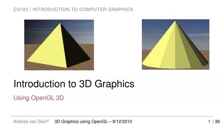
Introduction to 3D Graphics Using OpenGL 3D 3D Graphics using OpenGL – 9/12/2013 / 38
Classical Graphics Pipeline • Mesh objects with 3D polygons (triangles or quads usually) • Apply material properties to each object • Texture map polygons as needed • Light scene • Place camera • Enjoy the view 3D Graphics using OpenGL – 9/12/2013 / 38
Why OpenGL for 3D? • Widely used in industry and academia for interactive or real-time 3D graphics • Fixed-function API (OpenGL 1.x) assists rapid prototyping of simple 3D scenes with “classical” lighting effects • Experiment with simple ideas quickly 3D Graphics using OpenGL – 9/12/2013 / 38
3D Polygons (1/2) • Material specification • Describes the light reflecting properties of the polygon • Color, shininess, reflectiveness, etc. float color[] = { 1.0, 1.0, 0.3, 1.0 }; // Pale yellow, opaque glMaterialfv(GL_FRONT, // Color of front (visible) faces GL_DIFFUSE, // “Base” color (more later) color); // Pass in the R/G/B/A color values 3D Graphics using OpenGL – 9/12/2013 / 38
3D Polygons (2/2) • OpenGL defaults to a right-handed coordinate system • 3D polygons are defined like 2D polygons: glBegin(GL_TRIANGLES); glVertex3f(0, 75, 0); glVertex3f(-50, 0, 50); glVertex3f(50, 0, 50);glEnd(); • This defines one triangle • Coordinate values are arbitrary - can set virtual camera up to capture any size scene, so use convenient values • Remember counter-clockwise winding order! 3D Graphics using OpenGL – 9/12/2013 / 38
Complexities of Light Reflection from Surfaces – Need to Know Intensity and direction of all light that strikes a point on object's surface, whether directly from light source or after many bounces from other objects ( global illumination) How an object's surface appears tous as it reflects, absorbs, and diffracts light (“material properties”) Location of eye relative to scene Distribution of intensity per wavelength of incident light Human visual system (HVS) and itsdifferential response to light stimuli Lights may have geometry themselves Lighting/illumination models address these complexities (except for HVS) 3D Graphics using OpenGL – 9/12/2013 / 38
An Imperfect World – Model via Approximations • Classic lighting models (also called illumination or reflection models, not to be confused with shading models discussed later) developed at the dawn of raster graphics in early 70s. • Epicenter at University of Utah where Ivan Sutherland worked with David Evans • Spawned the Evans & Sutherland flight simulator (with graphics) business • Other pioneers: • Gouraud (shading model – filling in interior pixels from colors at vertices of a triangle) • Phong (lighting and shading models) • Newell (the Utah teapot (SIGGRAPH icon), meshing algorithms) • Clark (geometry engine, Silicon Graphics, Netscape) • Warnock (Hidden Surface Elimination, Adobe) • Catmull (splines, Pixar) • etc... 3D Graphics using OpenGL – 9/12/2013 / 38
An Imperfect World • Back then: • CPUs > 4 orders of magnitude less powerful, no GPU to speak of, just plot pixels • memory limited (measured in KB!) • Even on today's machines, a physically accurate light simulation requires computational power beyond the capabilities of supercomputers! 3D Graphics using OpenGL – 9/12/2013 / 38
Lighting (Illumination) Models (1/2) • Idir = measure of intensity of directional light (all rays parallel) at point of contact with surface • θ = angle between surface normal (n) and vector from light source ( ) Facing light source: Maximum reflection • Note: Idirand all the other quantities in the lighting model are fractions between 0 and 1. • These units are also completely arbitrary and not physically based! to light source: No reflection In between: Some fraction of light reflected • Color of point on surface dependent on scene lighting and surface material • First approximation: model diffuse reflection from a matte surface (light reflected equally in all directions, viewer-independent) based only on angle of surface normal to light source • Modeling light "drop-off“ with angle to light • Lambert's diffuse-reflection cosine law • for reflected light intensity I 3D Graphics using OpenGL – 9/12/2013 / 38
Lighting (Illumination) Models (2/2) • Lambert light attenuation based on surface's angle to light source • Visualization of Lambert's law in 2D Note: we will characterize the intrinsic material properties of the object with RGB values. For example, the greater the R, the more reddish the object will appear under white light. 3D Graphics using OpenGL – 9/12/2013 / 38
Shading Rule (1/6) www.sklardevelopment.com/graftext/wpf/3d • Goal: finding color at each pixel, preferably w/o having to evaluate a full lighting model at each pixel • First approach: Lambert's cosine law (flat/constant shading for whole facet) • faceted appearance, perfect for this rectangular pyramid. • What if we want to approximate a rounded object? • Lambert-shaded, faceted; appearance is no longer ideal 3D Graphics using OpenGL – 9/12/2013 / 38
Shading Rule (2/6) • First solution: increase the number of polygons • Better shape approximation, more expensive to render • Ultimately, still faceted when rendered (higher poly count = less faceted) • Adaptive meshing is an improvement - more polygons in areas of high curvature “Utah Teapot” by Martin Newell 3D Graphics using OpenGL – 9/12/2013 / 38
Shading Rule (3/6) • Get this: • Want this: faceted shading smooth shading 3D Graphics using OpenGL – 9/12/2013 / 38
Shading Rule (4/6) The normal at a vertex is the same as the plane normal. Therefore, each vertex has as many normals as the number of planes it helps define. Only one vertex normal per vertex; average of face normals of the faces the vertex is part of • Gouraud smooth shading • compute lighting equation at each vertex of mesh • linearly interpolate vertex color values to get colors at all points • weighted averaging: the closer the point is to a vertex, the more it is influenced by that vertex • How do we determine vertex colors? Need a normal… • Vertex normals are an artifice; the normal is mathematically undefined since a vertex is a discontinuity • we hack around this by averaging 3D Graphics using OpenGL – 9/12/2013 / 38 Faceted Smooth
Shading Rule (5/6) 2D curve approximation (vertex normals in green) Vertex normals shown in color, face normals in black mesh approximation • Vertex normals • normals not specified explicitly • if vertex used by only one face, normal is set to face's normal • otherwise, normal is set to average of normals of all faces sharing it • if mesh is not too coarse, vertex normal is a decent approximation to the normal of modeled surface closest to that vertex • adaptive meshing adds more triangles in areas with rapid changes in curvature 3D Graphics using OpenGL – 9/12/2013 / 38
Shading Rule (6/6) • OpenGL provides either flat or Gouraud shading • to get the default flat shading, OGL uses the surface normal for vertices of the same facet (each vertex gets nnormals, where n is the number of facets it is a part of) • to get smooth shading, you must specify a single shared normal for each vertex in the object 3D Graphics using OpenGL – 9/12/2013 / 38 Faceted Smooth
Interpolation vs Flat Shading Summary 3D Graphics using OpenGL – 9/12/2013 / 38
Reflectance (Illumination, Lighting) Model (1/8) • Non-geometric lights: • Ambient: crude approximation to inter-object reflection, all surfaces receive same light intensity • Directional: illuminates all objects equally from a given direction; light rays are parallel (models sun) • Geometric lights: • Point: Originates from single point, spreads outward equally in all directions • Spotlight: Originates from single point, spreads outward inside cone’s directions 3D Graphics using OpenGL – 9/12/2013 / 38 Spotlight Directional Point
Reflectance Model (2/8) // ambient term is RGBA quadruple float ambient[] = { 0.2, 0.2, 0.2, 1.0 }; // vectors are XYZW quadruple, w = homogeneous coordinate (see Transformations lecture) float position[] = { 10.0, 5.0, 8.0, 1.0 }; float direction[] = { 1.0, 2.0, 3.0, 0.0 }; // Specify color(s) glLightfv(GL_LIGHT0, // or GL_LIGHT1, GL_LIGHT2, etc GL_AMBIENT, // or GL_DIFFUSE, or GL_SPECULAR ambient); // or diffuse / specular color, respectively// Point light because position’s w = 1 glLightfv(GL_LIGHT0, GL_POSITION, position); // Directional light because direction’s w = 0 glLightfv(GL_LIGHT0, GL_POSITION, direction); GL_POSITION is not a typo! OpenGL uses a linear algebra trick (homogenization) for light directions. More later in the course. 3D Graphics using OpenGL – 9/12/2013 / 38
Reflectance Model (3/8) • Many models exist to approximate lighting physics – the more accurate, the more computation required • OpenGL: Phong reflection model , survives today (though crude) • approximates lighting by breaking down into three components: ambient, diffuse, specular • can think of these as coincident layers, each with its own characteristics, we sum them to get the final result • non-global illumination model – model does not handle inter-object reflections Note: The book uses a similar graphic that features the familiar teapot 3D Graphics using OpenGL – 9/12/2013 / 38
Reflectance Model (4/8) - OGL differs slightly from WPF in book • Equation is wavelength-dependent; approximate with separate equations for • All values unitless real numbers between 0 and 1 Ambient Component Diffuse Component Specular Component Evaluates reflected light i at a single point 3D Graphics using OpenGL – 9/12/2013 / 38
Reflectance Model (5/8) • Variables • = wavelength / color component (e.g. R, G, and B) • = total amount of light reflected at the point • = intensity of light incident at a specific point on surface • = intensity of ambient light used in scene; similar for diffuse, specular • = innate color of object's material at specific point on surface (RGB approximation) • Ambientcomponent • effect on surface is constant regardless of orientation, no geometric information • total hack (crudest possible approximation to global lighting based on inter-object reflection), but makes all objects a little visible - scene looks too stark without it 3D Graphics using OpenGL – 9/12/2013 / 38
Reflectance Model (6/8) • Diffuse component (R component shown below, same for G, B) - viewer independent! • uses Lambert's diffuse-reflection cosine law • = light’s diffuse color • = innate color of object's diffuse material property at specific point on surface • = Lambert's attenuation factor where is the angle between normal and light vector 3D Graphics using OpenGL – 9/12/2013 / 38
Reflectance Model (7/8) • Specular Component (for R) – viewer-dependent • highlights seen on shiny objects (metal, mirrors, etc.) • cosine-based attenuation factor ensures highlight only visible if reflected light and viewer are closely aligned • n = specular power, how "sharp" highlight is – the sharper, the more intense • specular highlight of most metals are the color of the metal but those on plastic, shiny apple, pearl, etc. are mostly the color of the light (see Materials chapter 27) e = viewpoint r = reflected image of light source ℓ = vector from the light source n = surface normal δ= angle between eand r n = specular coefficient Note: OpenGL uses a slightly different lighting model called Blinn-Phong. See 14.9.3 3D Graphics using OpenGL – 9/12/2013 / 38 Specular falloff of cosn
Reflectance Model (8/8) • Attenuation factor • Used in diffuse and specular light calculation: • Directional lights have no attenuation (infinitely far away) • Geometric lights (point lights, spot lights) get dimmer with distance • Inverse square law • Area covered increases by square of distance from light • Thus, light intensity is inversely proportional to the square of the distance from light • A light twice as far away will be one quarter as intense • Though the physics say inverse square law, it doesn't always look good in practice so OpenGL lets you choose the attenuation function (quadratic, linear, or constant) d d d 3D Graphics using OpenGL – 9/12/2013 / 38
Texture Mapping • Goal: adding more detail to geometry of scene without adding complexity • Solution: texture mapping • used extensively in video games, e.g., for backgrounds, billboards • also used for many other techniques such as level-of-detail management • cover the mesh's surface in stretchable "contact paper" with pattern or image on it • in general, difficult to specify mapping from contact paper to every point on an arbitrary 3D surface • mapping to planar polygons is easy: specify mapping for each vertex and interpolate to find mapping of interior points • Specifying "texture point" mapped to particular vertex • requires coordinate system for referring to positions within texture pixmap • convention: • points on pixmap described in abstract floating-point "texture-coordinate system" • axes labeled u and v, range 0 to 1. • origin located at the upper-left corner of the pixmap 3D Graphics using OpenGL – 9/12/2013 / 38 (0,0) U axis (1,0) V axis (0,1)
Texture Mapping Example (details clarified in lab) QImageimg;GluinttextureID; // Load image from file on disk (using Qt)img.load(“sand.gif”);img = img.convertToGLFormat(img); // Create texture on graphics deviceglGenTextures(1, &textureID); // 1: generate one texture only// Load image data into textureglBindTexture(GL_TEXTURE_2D, textureID);glTexImage2D(GL_TEXTURE_2D, 0, GL_RGBA, img.width(), img.height(), 0, GL_RGBA, GL_UNSIGNED_BYTE, img.bits()); Full glTexImage2D Documentation: http://www.opengl.org/sdk/docs/man/xhtml/glTexImage2D.xml 3D Graphics using OpenGL – 9/12/2013 / 38
Texture Mapping UV Coordinates • We are mapping from the two coplanar triangles in the 3D model to a texture map • Texture map uses UV texture coordinates • Texture mapping arbitrary solids is much harder – we’ll study this later 3D Graphics using OpenGL – 9/12/2013 / 38
Texture Mapping Example // Draw the desert floor using the textureglBegin(GL_QUADS);glTexCoord2f(0, 0); //map (0,0) in the texture map to the following vertexglVertex3f(-9999, 0, 9999); //works with arbitrary vector coordinatesglTexCoord2f(1, 0);glVertex3f(9999, 0, 9999);glTexCoord2f(1, 1);glVertex3f(9999, 0, -9999);glTexCoord2f(0, 1);glVertex3f(-9999, 0, -9999);glEnd(); 3D Graphics using OpenGL – 9/12/2013 / 38
Texture Mapping (Tiling) • Create a brick wall by applying brick texture to plane • Produces realistic-looking image, but very few bricks in wall • Tiling increases number of apparent bricks 3D Graphics using OpenGL – 9/12/2013 / 38
Texture Mapping (Stretching) • Create a sky backdrop by applying a sky image to a plane • Would look unnatural if tiled • Stretch to cover whole plane • OpenGL lets you specify tiling and stretch factors 3D Graphics using OpenGL – 9/12/2013 / 38
Camera (1/3) • Camera Properties: • Perspectiveor Orthographic • Position: placement of camera • Look Direction: direction camera is aimed (vector determining lens axis) • Up Direction: rotates camera about look vector, specifying which way is “up” – must not be collinear to the look vector • Far-Plane Distance: objects behind do not appear • Near-Plane Distance: objects in front do not appear • Field Of View: (Height Angle) • Aspect Ratio (Relative width and height) 3D Graphics using OpenGL – 9/12/2013 / 38
Camera (2/3) Center of Scene (used to compute LookAtDirection) • Perspective Projection Projection ofUp Direction Up Direction FOV in y-direction Position y Near-Plane Distance Far-Plane Distance 3D Graphics using OpenGL – 9/12/2013 / 38
Width Far distance Height Center of scene Near distance Projection of up vector Up vector Position Camera (3/3) • Orthographic Projection 3D Graphics using OpenGL – 9/12/2013 / 38
OpenGL Camera • Support for perspective and orthographic cameras. • Example for perspective camera:// Projection matrix captures the static properties of the cameraglMatrixMode(GL_PROJECTION);gluPerspective(45, // Field of view window->width() / window->height(), // Aspect ratio 0.02, 1000); // Near, far plane distances// Modelview matrix captures positioning and orientation of the sceneglMatrixMode(GL_MODELVIEW);gluLookAt(54, 51, 247, // Camera position (X, Y, Z) 2, 0, 9, // Center of scene (X, Y, Z) 0, 1, 0); // Up direction (X, Y, Z) 3D Graphics using OpenGL – 9/12/2013 / 38
WPF3D Lablets (1/2) • Hands on exploration of concepts discussed in this lecture • Modeling smooth surfaces www.sklardevelopment.com/graftext/wpf/3d 3D Graphics using OpenGL – 9/12/2013 / 38
WPF3D Lablets (2/2) • Lighting and shading model www.sklardevelopment.com/graftext/wpf/3d 3D Graphics using OpenGL – 9/12/2013 / 38
Book Sections • Intro • Chapter 6 3D Graphics using OpenGL – 9/12/2013 / 38