Download
1 / 13
140 likes | 364 Views
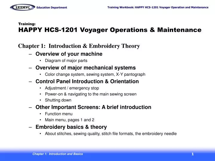
Training: HAPPY HCS-1201 Voyager Operations & Maintenance. Chapter 1: Introduction & Embroidery Theory Overview of your machine Diagram of major parts Overview of major mechanical systems Color change system, sewing system, X-Y pantograph Control Panel Introduction & Orientation

E N D
Training:HAPPY HCS-1201 Voyager Operations & Maintenance Chapter 1: Introduction & Embroidery Theory • Overview of your machine • Diagram of major parts • Overview of major mechanical systems • Color change system, sewing system, X-Y pantograph • Control Panel Introduction & Orientation • Adjustment / emergency stop • Power-on & navigating to the main sewing screen • Shutting down • Other Important Screens: A brief introduction • Function menu • Main menu, pages 1 and 2 • Embroidery basics & theory • About stitches, sewing quality, stitch file formats, the embroidery needle Chapter 1: Introduction and Basics
Overview: A Quick Tour of the Machine tree Manual needle selector knob Screen contrast adjustment upper-tensioning knobsthread break sensorslower tensioning knobs Thread posts base EmergencyStop Switch Ports Serial USB LAN fuses power X-carriagetubular arm Compact flash slot Rotary hook door / bobbin cover Oiling guide/instructions cylinder arm Main power switch: Press and hold continuously for 1-2 sec. to power on Table area beneath cylinder arm:: for tubular goods, table or other object under cylinder arm can provide support. For garment. However, cap driver requires that surface be at least 4” below level of feet. Chapter 1: Introduction and Basics
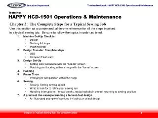
take-up lever “crank” cam converts spinning motion to up-and-down motion of needle bar needle bar bobbin sits in basket of rotary hook lower shaft rotary hook spins on lower shaft Side view of machine: head and sewing arm • 2. Sewing System • Take-Up Lever • Needle bar • Rotary hook / bobbin • 1. Color Change System • Moving head • Thread cut system Overview: 3 key mechanical systems Moving head Currently selected needle is the one directly over the presser foot. During a thread trim: (1) Needle descends, and thread is cut below needle plate between a fixed & moving knife. (2) Then, when needle comes back up, the “catcher” hook grabs the cut end and “docks” it into the thread holder. 3. X-Y Pantograph X-direction Y-direction x-carriage Chapter 1: Introduction and Basics
Emergency Stop Control Panel Intro: Quick Orientation This button is used to shut the machine off in case of emergency. The machine will remember the last sewn stitch but may be slightly off alignment when re-started. To recover from emergency stop, clear any problem, un-twist the button to re-set it and power on normally. The machine will not power on unless the button is re-set to the “on” position. Emergency Stop P. FOOT Chapter 1: Introduction and Basics
Initial Power-On Control Panel Intro: Power On to the Main (Drive) Screen Power on your machine with the black switch located on the side of the machine. The screen below appears. This startup screen appears at power-on. Reminder tells you to press “SET”. P. FOOT Next: How to enable/disable on-board help on startup Chapter 1: Introduction and Basics
Getting to the Main Screen Control Panel Intro: Power On to the Main (Drive) Screen The Guide or on-board help function appears by default when pressing SET to continue. You can disable this feature as shown below to go instead directly to the main “drive” screen. The “guide”, or on-board help screen appears by default. Check hereif you don’t need to view the guide next time you start the machine. P. FOOT Press ESC from here to get to the main “drive” screen. Next: The main (drive) screen Chapter 1: Introduction and Basics
Getting to the Main Screen Control Panel Intro: Power On to the Main (Drive) Screen This is the main “drive” screen. The machine will not sew or accept design transfers via cable unless it is in this mode. Learn how to get to this screen either from power-on or by pressing ESC. Origin Symbol: shows that the current design is at the origin and ready to begin. This is the main “drive” screen. Active needle: current needle P. FOOT Chapter 1: Introduction and Basics
The FUNC menu and shut-down Control Panel Intro: Other Important Screens In addition to the main Drive screen, there are 2 other important menus to know: The Main Menu (shown on the next page) and the Function menu, shown below, which is accessed by pressing FUNC. The functions of this menu are used during sewing and will be discussed later. This is the main FUNC screen. Turn off the machine with this option. This helps protect the machine. P. FOOT Chapter 1: Introduction and Basics
The Main Menu The other - and most important - menu is the Main Menu, accessed from the main Drive screen by pressing MENU as shown below. Control Panel Intro: Other Important Screens P. FOOT Press the MENU button to get to the main menu. Chapter 1: Introduction and Basics
The Main Menu This is page 1 of the main menu. In the next chapters we’ll show the functions in-depth for 6 of its functions, which you’ll use regularly as you sew with your machine. Control Panel Intro: Other Important Screens P. FOOT Press the ESC key exits you to the main (drive) screen. Navigate to a menu item using these 4 blue arrow keys,then press SET to enter the screen for that item. Chapter 1: Introduction and Basics
The Main Menu This is page 2 of the main menu. Control Panel Intro: Other Important Screens P. FOOT Press the ESC key exits you to the main (drive) screen. Navigate to a menu item using these 4 blue arrow keys,then press SET to enter the screen for that item. Chapter 1: Introduction and Basics
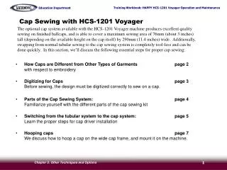
Key Embroidery Basics / Theory • About Stitches : • All stitches are formed by a ½ loop of colored thread looped with ½ loop of bobbin thread. • Max and minimum length: Must be between 1mm (.04 inch) and 12.7mm (1/2 inch). Too short causes thread breaks. Too long, stitches are too loose. • 3 Major Factors Affecting Sewing Quality that you can control: • Tension – once properly set, should rarely require re-adjustment. We will cover this in class. • Hooping – proper hooping is a must. Not too tight, not too loose. We will cover this in class. • Digitizing – hire a digitizing service and/or learn how to digitize in digitizing classes. • Sewing file format used in embroidery: DST • All commercial machines read this format • Does not have color information – must load the design into the machine AND tell it which colors to sew. • Limited in editability – the design must be sewn at the size it was digitized. • About Embroidery Thread • Upper (colored) thread • Can be polyester or rayon, usually polyester. Standard is 40 weight • Comes in several sizes: 5,000 meter cones to 1,000 meter cones. • Handle carefully: physical contact, oil/dirt, moisture can prevent it from unspooling smoothly and catch • Bobbin thread • L-type, approximately 350 yards per spool. Bobbin thread will have to be changed more frequently than upper thread • Lasts approximately 25,000 to 60,000 stitches Chapter 1: Introduction and Basics
Key Embroidery Basics (continued) • Embroidery Needles: • Type DB-K5, standard size is 75/11 ballpoint for most applications. Alternate needle for sewing caps and other tightly-woven goods (heavy canvas) is 80/12 sharp point for better penetration • The width of the shaft of an embroidery needle limits the the finest possible detail (the smallest possible stitch). Standard size (75/11) needles are .75 mm across, so stitches must be at least a little wider than the hole that the needle punches in the fabric (minimum distance 1mm) • Needles are subject to wear! Over time, burred surfaces and other wear can cause problems. Be prepared to change needles frequently especially with heavy use. butt Front view Side view Shank – rounded. Does not have a flat spot blade or shaft Scarf – faces towards the back of the machine Groove – allows you to find the front of the needle by feel. Chapter 1: Introduction and Basics