Download
1 / 23
230 likes | 322 Views
Characteristic Impedance Contnd. Air Dielectric Parallel Line Coaxial Cable. Where: D = spacings between centres of the conductors r = conductor radius. Velocity Factor. The speed at which an energy is propagated along a transmission line is always less than the speed of light.

E N D
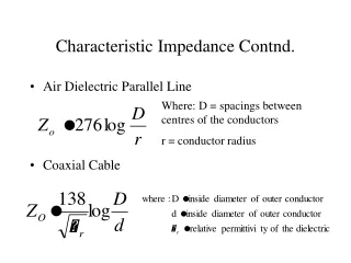
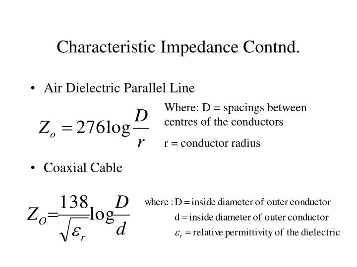
Characteristic Impedance Contnd. • Air Dielectric Parallel Line • Coaxial Cable Where: D = spacings between centres of the conductors r = conductor radius
Velocity Factor • The speed at which an energy is propagated along a transmission line is always less than the speed of light. • Almost entirely dependant upon the dielectric constant • Propagation velocity of signal can vary from 66% (coax with polyethylene dielectric) to 95%(air).
Response of Line • CONDITIONS • Step Impulses • Assume lossless line and infinite length with Zo equal to characteristic impedance of the line • Discuss: -Reflections along a line of finite length that is: a.) Open at point of termination (end of line) b.) Shorted at point of termination c.) Matched load at point of termination
Open Circuited Line • Switch is closed and followed by a surge down line. • How much of the source voltage appears across the source? (V/2) • What is the state of voltage and current at the end of the line? • For what time frame do the initial conditions exist? (2T) • What is the relative direction of incident and reflected current?(opposite)
Short Circuit Line • What is the state of voltage at the source prior to 2T? (V/2) • What is the state of voltage and current when the surge reaches the load? (V=0 and I depends on system characteristics) • What is the direction of incident and reflected current? (same)
Pulse Input To Transmission Line • With a matched line the load absorbs energy and there is no reflection • Open circuit has positive reflections • Short Circuit has negative reflections • REFLECTION COEFFICIENT(Gamma) - Open circuit line > gamma = 1 - Matched line > gamma = 0 - Short circuit line > gamma = -1
Traveling Waves Along A Line • Assume a matched line and a sinusoidal signal source. • Traveling wave • After initial conditions a steady state situation exists. • Signal will appear the same as the source at any point on the line except for time delay. • Time delay causes a phase shift ( one period = 360 degrees)
Standing Waves • Assume a transmission line with an open termination, a reasonably long line and a sinusoidal source • After initial reflection the instantaneous values of incident and reflected voltage add algebraically to give a total voltage • Resultant amplitude will vary greatly due to constructive and destructive interference between incident and reflected waves
Standing Waves contnd. • Reminder: A sine wave applied to a matched line develops an identical sine wave except for phase. • If the line is unmatched there will be a reflected wave. • The interaction of the two travelling waves (vr and vi) result in a standing wave. • SWR = Vmax/Vmin
Sample question • What length of RG-8/U (vf = .66) would be required to obtain a 30 degree phase shift at 100 Mhz?