Download

1 / 31
0 likes | 1 Views
Language: English<br>Format: PDF<br>Platform: Windows Phone, Ipad and Mac<br>Delivery: Instant Download After Payment.

E N D
953C TRACK LOADER BBX 00001-UP Printed by Heavy Equipment Manuals v2.20 Printed in U.S.A Heavy Equipment Manuals
This is the sample of the sample click on The download link for complete manual DOWNLOAD LINK For some reason if link does not work download this pdf and then click
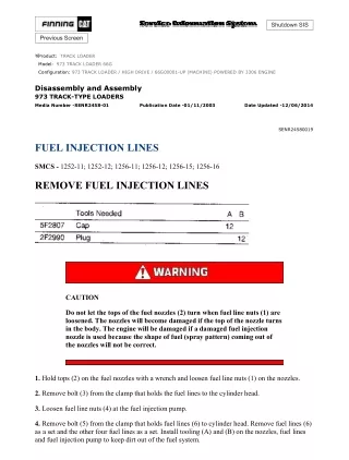
Product: TRACK LOADER Model: 953C TRACK LOADER BBX Configuration: 953C TRACK-TYPE LOADER BBX00001-UP (MACHINE) POWERED BY 3126B Engine Disass embly and Assembly Flexxaire Fan Media Number - RENR3699-07 Publication Date -01/ 02/ 2012 Date Updated - 21/ 06/ 2016 i01739978 Control System - Remove and Install SMCS - 1356-010-YC General Installation Installation of the Mark I Control System Illustration 1 g00564778 Mark I Control System (1) Mark I control box (2) AUTO-purge timer (3) Cable for remote display (4) Remote display (5) Pigtail
(6) Actuator (7) Temperature and ground cable (8) Temperature sensor (9) Position sensor (10) Power cable 1. Mount control box (1) in the operator's compartment. The mounting location should meet the following criteria: Minimal debris and vibration Safe from water that is high pressure Accessible for future adjustments or changes in setup The control box should be mounted in a vertical position, and vibration mounts that are supplied with the controller should be installed. 2. AUTO-purge timer (2) is located near control box (1). Connect the end of the cable for AUTO-purge timer (2) to the plug end of the cable for the AUTO-purge timer on control box (1). 3. Cable for remote display (3) may not be required for all installations. Connect the end of the cable for remote display (3) to the plug end of AUTO-purge timer (2). Connect the plug end of cable for remote display (3) into the end of the pigtail for remote display (4). 4. Mount remote display (4) on the dash or another convenient location. The remote display should be visible and accessible to the operator. Connect the end of the cable for remote display (4) to the plug end of the cable for remote display (3). 5. Connect the end of pigtail (5) to the plug end of the cable for control box (1). Pigtail (5) splits into a harness with three connectors. One end goes to actuator (6). One end goes to temperature sensor (8). One end goes to position sensor (9). 6. The following steps are for installation of actuator (6):
Illustration 2 g00592444 (1) Actuator (2) Actuator rod (3) Actuator collar (4) Setscrew (5) Operator fork (6) Hitch pin (7) Mechanical stop (8) Position sensor (9) Alignment plate (10) Actuator clevis a. Remove hitch pin (6). b. Position operator fork (5) against mechanical stop (7). c. Manually turn actuator rod (2) outward until the rod is fully extended. When the rod reaches the end of travel, the actuator motor can be felt turning. d. Retract actuator rod (2) by the rotating actuator rod by 180 degrees. The actuator motor should not turn. e. Slide actuator (1) through actuator collar (3). Verify that the actuator collar is oriented so that setscrews (4) are facing away from actuator clevis (10). f. Retracting actuator rod (2) by 1/4 turn may be required in order to line up the hole in actuator rod (2) with the hole in operator fork (5). g. Insert hitch pin (6) through operator fork (5) and actuator rod (2). h. Verify that operator fork (5) is against mechanical stop (7). Make sure that the actuator motor is oriented in the correct position. The actuator motor must be clear of obstructions. Rotate the actuator in the collar prior to tightening setscrews (4).
i. Apply 9S-3263 Thread Lock Compound to setscrews (4) and install the setscrews. Tighten the setscrew to a torque of 16 N·m (12 lb ft). Note: Do not tighten setscrews more than 1.5 threads below the surface. j. Connect the end of the cable for the actuator to the red and yellow plug of pigtail (5). 7. Connect the end of temperature and ground cable (7) to the plug with green and black wires of pigtail (5). The ground wire (green) is secured with a bolt that threads in to the support arm of the fan assembly. The brown lead wire is connected to the top of temperature sensor (8). 8. Thread temperature sensor (8) into the engine block. An area that is close to the water temperature regulator is recommended. Temperature sensor (8) comes with three thread adapters. The brown lead wire of temperature and ground cable (7) connects to the top of temperature sensor (8). Illustration 3 g00918804 (1) Mounting bracket for the position sensor (2) Bolt (3) Alignment plate (4) Mounting nut for the position sensor (5) Position sensor (6) Washer (7) Capscrew 9. The following steps are for installation of position sensor (9): a. Place mounting bracket (1) for the position sensor against alignment plate (3). b. Thread bolt (2) into mounting nut (4) for the position sensor through alignment plate (3) and position sensor mounting bracket (1). Tighten bolt (2) to a torque of 16.3 N·m (12.0 lb ft). c. Place position sensor (5) in the correct location. d. Put washer (6) on capscrew (7). Thread capscrew (7) into mounting nut (4) for the position sensor through position sensor (5).
e. Connect the plug end of the cable for position sensor (5) to the end of the pigtail. 10. Connect the plug end of power cable (10) to the end of the power cable for the control box. White wire - This wire connects to a 10 Amp fuse or to a circuit breaker. The power source that is being used must allow power to the control box when the engine is not running. Black wire - This wire connects to the main disconnect or a different ground location. Installation of the Mark III Control System Illustration 4 g00573394 Mark III control system (1) Mark III control box (2) Power cable (3) Extension cable for remote display (4) Remote display (5) Extension cable for temperature sensor (6) Cable for temperature sensor (7) Ground collar (8) Temperature sensor (9) Extension cable for actuator (10) Actuator (11) Screw (12) Mounting bracket (13) Vibration mount (14) Washer
(15) Nut (16) Cable for remote calibrator (17) Remote calibrator (18) Pressure switch 1. Mount control box (1) in the operator's compartment. The mounting location should meet the following criteria: Minimal debris and vibration An area that is away from high pressure washes Accessible for future adjustments and changes in setup The control box should be mounted in a vertical position and the vibration mounts that are supplied with the control box should be installed. 2. Install temperature sensor (8) with the NPT bushing that is supplied. The sensor should be installed in the water jacket of the engine. The most preferable location for the temperature sensor is near the coolant temperature regulator. This will allow the sensor to sense maximum water temperature. 3. Route extension cable for temperature sensor (5) from the control box to the temperature sensor. Connect cable for temperature sensor (6) to extension cable (5). Connect the black wire to the ground collar. Install the ground collar around the hex portion of the temperature sensor and tighten the clamping screw. Connect the white wire to the top of the temperature sensor. 4. Route extension cable for actuator (9) from the control box to the actuator. 5. Connect power cable (2). Red wire - This wire connects to a 10 Amp fuse or to a circuit breaker. The connection should be made to a circuit that is isolated during operation of the starter. This circuit should not be powered when the ignition key is in the OFF position. Black wire - This wire connects to the main disconnect or a stable ground location. 6. Mount remote display (4) on the dash or another convenient location. The remote display should be visible and accessible to the operator. Connect the remote display to the control box with an extension cable for remote display (3). If it is not practical to mount the remote display in the operator's compartment, the display should be mounted in an enclosed area that will not be exposed to the elements. The display is not required for operation of the control box. 7. Applications that use the radiator fan to cool the A/C condenser core should use pressure switch (18). The pressure switch should be installed on the high pressure side of the compressor. Remove the jumper wire from cable for temperature sensor (6) and plug in pressure switch (18). When the condenser core reaches a set pressure, the fan is put into full pitch in order to cool the condenser core. 8. The following steps are for installation of actuator (10):
Illustration 5 g00592173 (1) Actuator (2) Actuator rod (3) Actuator collar (4) Setscrew (5) Operator fork (6) Hitch pin (7) Mechanical stop (8) Alignment plate (9) Actuator clevis a. Remove hitch pin (6). b. Position operator fork (5) against mechanical stop (7). c. Manually turn actuator rod (2) outward until the rod is fully extended. When the rod reaches the end of travel, the actuator motor can be felt turning. d. Retract actuator rod (2) by rotating actuator rod (2) by 180 degrees. The actuator motor should not turn. e. Slide actuator (1) through actuator collar (3). Verify that the actuator collar is oriented so that setscrews (4) are facing away from actuator clevis (10). f. Retracting actuator rod (2) by 1/4 turn may be required in order to line up the hole in actuator rod (2) with the hole in operator fork (5). g. Insert hitch pin (6) through operator fork (5) and actuator rod (2). h. Verify that operator fork (5) is against mechanical stop (7). Make sure that the actuator motor is oriented in the correct position. The actuator motor must be clear of obstructions. Rotate the actuator in the collar prior to tightening setscrews (4). i. Apply 9S-3263 Thread Lock Compound to setscrews (4) and install the setscrews. Tighten the setscrew to a torque of 16.3 N·m (12.0 lb ft).
Note: Do not tighten setscrews more than 1.5 threads below the surface. 9. Connect the end of the cable for the actuator to the plug end of the extension cable. Installation of Blaze Blocker This feature is integral to the control box. The required connector is part of the harness from the control box. The connector will receive the signal from the fire suppression system. Note: Before the circuit is tested, be sure that the canisters for the fire suppression system are disconnected in order to prevent the canisters from discharging when the circuit is energized. Reconnect the canisters after the test of the circuit is complete. 1. Locate the control box. 2. Determine whether the fire suppression system is manual or automatic. 3. Follow the appropriate procedure: a. Manual Fire Suppression System Install a switch that is normally open near the fire suppression plunger. Connect a 16 gauge wire from the common terminal of the switch to ground. Connect a 16 gauge wire from the other pole of the switch into pin 1 of a deutsche connector. The length of the signal wire will depend on the distance from the switch to the connector on the control box. Pin 2 of the deutsche connector is left empty. Connect the plug from the switch to the receptacle on the controller. Apply power to the control box and turn the switch ON. The control box will place the fan into the NEUTRAL position. The "PUSH" light and the "PULL" light on the remote display will be flashing as well as the T1 light and T2 light inside the control box. This indicates that the switch is wired properly and that blaze blocker is on. Move the switch to the OFF position in order to resume normal operation. When a fire is observed, the operator should flip the switch first. Then, the operator should activate the fire suppression system. b. Automatic Fire Suppression System Locate the warning alarm relay circuit. This circuit will activate a warning relay on the fire suppression system. This indicates that a fire has been detected. Connect a 16 gauge wire from the common terminal of the relay to ground. Connect a 16 gauge wire from the other pole of the relay into pin 1 of a deutsche connector. The length of the signal wire will depend on the distance from the switch to the connector on the control box. Pin 2 of the deutsche connector is left empty. Connect the plug from the relay to the receptacle on the controller. When the relay is energized, the control box will place the fan into the NEUTRAL position. The "PUSH" light and the "PULL" light on the remote display will be flashing as well as the T1 light and T2 light inside the control box. This indicates that the switch is wired properly and that blaze blocker is on. Copyright 1993 - 2020 Caterpillar Inc. Mon Sep 7 12:57:54 UTC+0530 2020 All Rights Reserved.
Product: T RACK LOADER Model: 953C T RACK LOADER BBX Config uration: 953C TRACK-T YPE LOADER B BX00001- UP (MACHI NE) POWERED BY 3126B Eng ine Disassembly and Assembly Flexxaire Fan Media N um ber - RE NR 3699 -07 Public ation Date - 01/ 02/ 20 12 Dat e Upd at ed - 21 / 06/ 20 16 i06636599 Hydraulic Actuated Fan - Assemble SMCS - 1356-016-HR Preliminary Fan Assembly Note: Refer to the Service Manual Disassembly and Assembly (Engine Supplement), "Reversible Fan - Assemble" for the Track Feller Buncher machines only on the assembly procedure. Note: Before you proceed, ensure that you know the correct model of the hydraulic actuated fan. Refer to Operation and Maintenance Manual, "Model View Illustrations" to identify the model of the fan. 1. Clean all surfaces and threads prior to assembly. 2. Make sure that all the parts are present for the assembly. 3. To ease assembly, lubricate all the seals and the O-rings as you assemble the fan. Note: Unless the instructions state otherwise, do NOT apply Loctite or any equivalent adhesives to any of the fasteners that contact aluminum parts. Main Shaft - Assemble
Illustration 1 (1) Hex through shaft (2) Bushing (3) Rod shaft (4) O-ring (5) Backup ring (6) Seal (7) External Seal (8) Hex nut (9) Backup ring (10) End cap (11) Bushing snap ring (12) Main shaft (13) Seal Retainer (14) Internal Seal (15) Piston (16) Backup rings (17) O-ring (18) O-ring (19) Snap ring g00906033 For reference, Illustration 1 pictures a cross section view of the main shaft that iscompletely assembled. 1. Position the main shaft in a vise.
Note: If an extension is used on the main shaft, apply a few drops of 4C-9506 Retaining Compound to the threads of the extension. Thread the extension and tighten the extension to a torque of 34 N·m (25 lb ft). 2. Clean the inside of the main shaft and seal retainer of all possible debris with 138-8441 Brake Cleaner. Illustration 2 g00906204 Illustration 3 (A) The correct position for the backup rings (B) The incorrect position for the backup rings g00906209 3. Place internal seal (14) into the seal retainer (13). 4. Insert both backup rings (5) on either side of the internal seal (13).
Note: Make sure that the ends of the backup rings are enclosed on each other properly. See Illustration 3 for the correct positioning of the ends of the backup rings. 5. Apply a small amount of grease on O-ring (4) to hold the O-ring in place. Place O-ring (4) in the O-ring groove of seal retainer (13). 6. Apply a thin coating of oil onto the inside of the internal seal. 7. Thread seal retainer (13) into the rear of main shaft (12). Note: Do NOT apply Loctite or equivalent adhesives to the threads of the seal retainer. 8. Use Snap-On S6183 Socket to tighten the seal retainer to a torque of (13) to 34 N·m (25 lb ft). 9. Slide rod shaft (3) through seal retainer (13) until the end of the hex through shaft (1) comes to rest against seal retainer (13). Repeat this step for the various sides of the hex through shaft until you find a position that gives no resistance except for the resistance from the seal. Note: Use a finger on the other side of the main shaft to help guide the rod shaft past the seal retainer. Note: When you are sliding the rod shaft past seal retainer (13), be careful not to damage the internal seal and/or the backup rings. Illustration 4 g00906297 10. Place external seal (7) onto piston (15). 11. Insert both backup rings (16) on either side of external seal (7). Note: Make sure that the ends of the backup rings are enclosed on each other properly. See Illustration 3 for the correct positioning of the ends of the backup rings. 12. Place internal O-ring (17) into the groove on piston (15). 13. Apply a thin coating of oil onto external seal (7) and onto O-ring (17) of the piston.
Illustration 5 g00906300 14. Push piston (15) into the rear of main shaft (12) and onto the end of rod shaft (3) until the piston rests against the shoulder of the rod shaft. Note: Some designs have a spacer that needs to be installed. The spacer is located between seal retainer (13) and the piston (15). Note: The orientation of the piston prior to installation is critical. There are two different styles of piston that are used. See Illustration 5 for the proper orientation. Note: Be careful when you slide piston (15) into main shaft (12) and onto the end of rod shaft (3). Do not damage external seal (7), backup rings (16), or O-ring (17). 15. Apply 9S-3263 Thread Lock Compound to the threads of hex nut (8). 16. Thread hex nut (8) onto rod shaft (3) and tighten the hex nut to a torque of 34 N·m (25 lb ft). Note: Slide the shafts and the piston in and out to make sure that the resistance is slight. 17. Push piston (15) until the piston comes to rest against seal retainer (13). Illustration 6 g00906341
18. Install backup ring (9) onto end cap (10). Note: Make sure that the ends of the backup rings are enclosed on each other properly. See Illustration 3 for the correct positioning of the ends of the backup rings. 19. Install O-ring (18) onto end cap (10). 20. Lubricate the O-ring with a thin coating of oil. 21. Insert end cap (10) into the rear of main shaft (12). 22. Insert rear snap ring (19) into main shaft (12) to secure end cap (10). Be sure that snap ring (19) is properly seated in the main shaft. Note: The square edge on the snap ring must be facing outward and the edge must be properly seated. If an extension to the main shaft is used in the assembly, install the snap ring into the main shaft extension. 23. Remove the main shaft from the vise. Mounting Main Shaft onto Mounting Bracket Illustration 7 g00906423 1. Thread hydraulic connectors (21) onto main shaft (12) by hand to correctly orient the connectors.
Note: If information on the orientation of the connectors is required, contact Flexxaire at (780) 930-6832. 2. Mount the fan mounting bracket into a horizontal position, onto a vertical mounting stand, or onto a vise. 3. Place main shaft (12) onto fan mounting bracket (22). Note: The proper orientation of the main shaft onto the fan mounting bracket must be kept when you assemble these parts together. This will keep the centerline of the fan assembly and the height of the engine mounting correct, and the hydraulic lines will connect correctly. 4. Apply 9S-3263 Thread Lock Compound onto the threads of fastener (20). 5. Install fastener (20) into fan mounting bracket (22) and tighten to the specification. 6. Secure hydraulic connectors (21) to main shaft (12), but do NOT tighten the connectors excessively. 7. If necessary, install the hydraulic hoses on the fan. Main Shaft - Pressure Check Performing a pressure check on the main shaft will ensure that all the seals are properly seated. If you do not perform a pressure check, several problems can arise. Such problems include leaking hydraulic fluid and inadequate hydraulic pressure that is needed to change the pitch of the blades. 1. Connect a hydraulic source with a shutoff valve and a hydraulic pressure gauge between the pressure source and the fan. Repeat this step on both lines. Ensure that the shutoff valve is in between the pressure source and the gauge. Note: If a hydraulic source is not available, a source of air can be used. 2. Pressurize the main shaft to a pressure that is equal to the normal operating pressure, and close the first shutoff valve. Repeat this step on the other line also. 3. Leave pressure to the main shaft for a minimum of 15 minutes. 4. Check for leaks around the main shaft. 5. If no leaks are detected, release the hydraulic pressure and remove the shutoff valve and the hydraulic pressure gauge from both of the lines. Note: If leaks are found during the pressure check of the main shaft, the main shaft must be disassembled and assembled again to rectify the problem. 6. Leave the hydraulic source connected to the hydraulic fittings to perform the “Bearing Carrier - Preassemble”. Bearing Carrier - Preassemble 1. During the assembly of the Pre-Bearing Carrier, main shaft (12) must remain mounted in the vertical position. Refer to Illustration 8.
Illustration 8 g00906491 2. Place internal fillet spacer (23) onto main shaft (12). Note: Not all assemblies will require an internal fillet spacer. If necessary, the beveled edge must match the edge of the radius on the main shaft. Refer to Illustration 9.
Illustration 9 g00906493 3. Push cups (28) into bearing carrier (27). 4. Slide first bearing cone (29) onto main shaft (12). 5. Slide bearing spacer (26) onto main shaft (12). 6. Slide shims (25) onto main shaft (12). Note: Measure thickness of the old shims and replace the old shims with new shims which are supplied in a bearing kit. 7. Set bearing carrier (27) onto the first bearing set that is on the main shaft. 8. Place the second bearing cone into the bearing carrier. 9. Thread locknut (24) onto the main shaft and tighten the locknut with a certified torque wrench to the specific value.
Illustration 10 g00906504 10. Mount a dial indicator that has a magnetic base onto a stable base such as the fan mounting bracket. 11. Use the indicator to measure the vertical movement of bearing carrier (27) on the main shaft (12). 12. Raise and lower the bearing carrier to measure the vertical movement. Perform this step without any load. Note: The vertical movement of the bearing carrier must be between the specified values. Refer to Table 1 for clearances. Table 1 Bearing Clearances Flexxaire Part Number Clearance Shims(1) Cone Cup Max Min 10029 10018 .001 .003 - 10027 10028 .001 .003 - 10166 10190 .001 .003 - 10487 10488 .001 .003 - 11320 11321 .001 .003 -
11978 11979 .001 .003 - 10034 10035 .001 .003 10240 10169 10170 .003 .005 10250 10611 10612 .003 .005 10250 10813 10814 .004 .007 11016 (1)The shims come in thicknesses of 0.002, 0.003, 0.005, and 0.010 inches. The maximum stack height of the shims should not exceed 0.8890 mm (0.035 inch). The maximum number of shims is 5. 13. Add and remove shims (25) to ensure that the vertical movement is within the specifications. 14. Remove the dial indicator from the assembly. 15. Remove locknut (24) from main shaft (12). Note: While you remove the components, stack the components in the same order. This will ease assembly later. 16. Lift off bearing carrier (27) and place the bearing carrier to the side. Place the top bearing on top of the locknut. 17. Remove shims (25), bearing spacer (26), and the lower bearing cone from main shaft (12). Bearing Carrier - Assemble
Illustration 11 g00906544 1. Clean the seal bore (30) of bearing carrier (27) with 138-8441 Brake Cleaner to remove any adhesives or debris. 2. Place bearing carrier (27) horizontally. 3. Apply 4C-9507 Retaining Compound and 169-5464 Quick Cure Primer to seal bore (30) of bearing carrier (27). Also, apply this adhesive to the bore surface of the seal. Coat the surfaces completely. Illustration 12 g00906549 4. Place bearing carrier (27) vertically so that the seal bore (30) is directed upward.
Illustration 13 g00906552 5. Place first main bearing cone (29) into the cup (32) of bearing carrier (27). 6. Press seal (31) into the seal bore until the face of the seal is flush with the edge of bearing carrier (27). Note: The seal must be square with the seal bore of the bearing carrier to ensure the proper seal. 7. Flip bearing carrier (27) so that the seal bore is facing downward on the work surface. Note: If the fan assembly contains a spool, proceed to "Main Shaft and Bearing Carrier Assembly for Fans with Spools". If the fan assembly does not contain a spool proceed directly to "Main Shaft and Bearing Carrier Assembly for Fans without Spools". Main Shaft and Bearing Carrier Assembly for Fans with Spools
Illustration 14 g00906559
Illustration 15 g00906562 1. Install pulley (33) onto bearing carrier (27). 2. Lubricate seal (31) with light oil. 3. Install bearing carrier assembly (27) onto main shaft (12). Note: When you slide seal (31) over the shoulder of main shaft (12), take care not to damage the seal. Also, make sure that no part of the lip of the seal is turned upward. 4. Install the spacer for the bearing carrier (27) and shims (25) onto main shaft (12). Note: When you install shims, place the smaller thicknesses first. Turn burrs upward on the main shaft. 5. Slide second bearing set (35) and lockwasher (34) onto main shaft (12). 6. Apply 4C-9506 Retaining Compound to the threads on the main shaft. Thread locknut (24) onto main shaft (12). Tighten the locknut to the correct specification. Note: The beveled edge of the locknut must face toward the lockwasher. Align one of the slots on the locknut with one of the tabs on the lockwasher. When you align the tab and the slot, always tighten the locknut. Never loosen the locknut when you are aligning the tab and the slot. 7. Bend the lockwasher tab onto the slot of the locknut.
Illustration 16 g00906570 8. Clean the O-ring groove and install O-ring (35) on the carrier. Note: Apply Steps 9 through 16 only if the flange and/or the oil dam were removed from the spool. Illustration 17 g00916982 9. Clean the O-ring groove on the spool and place O-ring (36) into the groove on spool (37).
Illustration 18 g00906578 10. Clean the face of flange (38) with 138-8441 Brake Cleaner. Place flange (38) onto spool (37) and align the holes. Note: In some assemblies, the bearing carrier contains an alignment screw which must be used to align the flange. 11. Hold the flange and the spool together, and flip over the combination. Do not dislodge the O- ring. 12. Apply 9S-3263 Thread Lock Compound to the last 9.52 mm (0.375 inch) of the fasteners. Note: This step is not applicable to FX 2000 Fans.
Illustration 19 g00917072 13. Insert fasteners (39) and tighten to the correct value.