Download
1 / 36
360 likes | 547 Views
InnoSys Quick Connect End Effecter Service and Maintenance Procedures. Nov. 19, 2007 Rev. B. InnoSys Quick Connect End Effecter Maintenance. 3 Bill of Material 4 – 5 End Effecter Exploded Views 6 - 10 Nose/Bearing Maintenance. Perform once per day

E N D
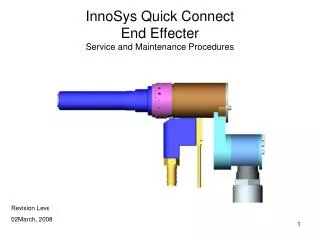
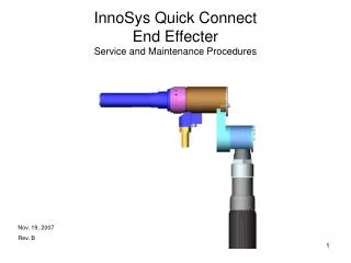
InnoSys Quick Connect End EffecterService and Maintenance Procedures Nov. 19, 2007 Rev. B
InnoSys Quick Connect End Effecter Maintenance • 3 Bill of Material • 4 – 5 End Effecter Exploded Views • 6 - 10 Nose/Bearing Maintenance. Perform once per day Replace Float Sleeves every 20,000 cycles • 11 - 13 Crowsfoot Attachment Lubrication Perform once per week • 14 – 19 Replacing the Drive Adapter • 20 – 22 Replacing Internal Components – Perform every 15,000 cycles • Backing Block • Thrust Bearings and Races • Spring Retainer • 23 - 27 Quick Connect Bearing Maintenance. Perform every 25,000 cycles • 28 –32 Replacing a Load Cell Perform as needed • 33 – 36 Process Overview
InnoSys QC Service ProcedureNose/Bearing Maintenance 1) With End Effecter in returned position as shown Return Sleeve will remain in this back (returned) position. Do not push in Input Shaft during this procedure. Return Sleeve is back Input shaft is extending slightly through front of nose 2) Unscrew and remove Nose Wire Boss is forward Make sure Bumper remains installed inside front part of Nose.
InnoSys QC Service ProcedureNose/Bearing Maintenance 3) Slide Float Sleeve off input shaft to expose input shaft balls. Do not push in on input shaft during this procedure. 4) Remove Balls, there are six in all. A magnet can be used to remove the balls.
InnoSys QC Service ProcedureNose/Bearing Maintenance 5) After removing Balls, slide the Nose Bearing off the Input Shaft. Clean Input Shaft and ID and OD of Nose Bearing. Do not use solvents on Nose Bearing. • Clean bearing holes and shaft. Use a magnet to remove metallic particles from holes. • Apply super lube to holes and outside of shaft .
InnoSys QC Service ProcedureNose/Bearing Maintenance 7) Slide Nose Bearing back on to Input Shaft. FloatSleeve Nose Bearing Nose 9) Slide Float Sleeve back onto Input Shaft. DO NOT APPLY GREASE TO OUTSIDE OF FLOAT SLEEVE or INSIDE OF NOSE . 8) Re-lubricate outside of Input Shaft and place balls back into holes. (Use Super Lube).
InnoSys QC Service ProcedureNose/Bearing Maintenance 10) Screw Nose of End Effecter back on to Cylinder, hand tighten.
InnoSys QC Service ProcedureCrows Foot Lubrication Crows Foot Attachment Nut Runner
InnoSys QC Service ProcedureCrows Foot Lubrication • Unscrew cap screws and • remove front plate to expose gears.
InnoSys QC Service ProcedureCrows Foot Lubrication Roller Bearing • Clean gears and reapply super lube to gears, bearing and inside of back plate. Back plate
InnoSys QC Service ProcedureReplacing the Drive Adapter Return Spring Crows Foot Attachment End Plate 1) Remove end plate, crows foot, and return spring from cylinder of end effecter.
InnoSys QC Service ProcedureReplacing the Drive Adapter 2) Remove spirol ring, drive key and drive adapter from input shaft. Spirol Ring Drive Adapter Drive Key
InnoSys QC Service ProcedureReplacing the Drive Adapter 3) Install new Drive Adapter and reinstall the Drive Key, aligned with slot of Input Shaft.
InnoSys QC Service ProcedureReplacing the Drive Adapter This two piece tool is required for installing the Spirol Ring at the end of the input shaft .
InnoSys QC Service ProcedureReplacing the Drive Adapter Place driver over top of mandrel. 4) Place Spirol Ring onto tapered mandrel of installation tool.
InnoSys QC Service ProcedureReplacing the Drive Adapter 5) Push the driver down expanding the ring until the ring snaps into the groove at the end of the input shaft.
Replacing Internal Components 3) After removing Drive Adapter (previous section) remove Retaining Ring and Dowel retainer. Retaining Ring Dowel Retainer
Removing Internal Components 4) Unscrew M5 cap screw and slide Wire Boss a short distance from cylinder of end effecter. 5) Push Dowel Pin down through hole of input shaft and out bottom of cylinder. Wire Boss Dowel Pin M5 Cap Screw
InnoSys QC Service ProcedureQuick Connect/Bearing Maintenance Push in Input Shaft. 1) After removing all Nose components, push the Input Shaft in. This action will unlock the Release Sleeve and allow it to be removed.
InnoSys QC Service ProcedureQuick Connect/Bearing Maintenance 3) After removing the Release Sleeve the Input Shaft will spring back to the extended or “return” position. 2) The Release Sleeve and Sleeve Spring can now be removed to expose the Quick Connect Balls.
InnoSys QC Service ProcedureQuick Connect/Bearing Maintenance 4) Balls and aligning Dowel Pin can now be removed and the holes of the Cylinder can be cleaned. 5) Replace the Balls and reinstall the alignment Dowel Pin. The Balls and Pin should be lubricated with Super Lube.
InnoSys QC Service ProcedureQuick Connect/Bearing Maintenance 6) Place Release Sleeve Spring back on face of Cylinder
InnoSys QC Service ProcedureQuick Connect/Bearing Maintenance Once the Release Sleeve is all the way down release the Wire Boss. The Wire Boss and Input Shaft will spring back to the extended “return” position and the Return Sleeve will be locked in place. Then, reinstall all Nose components. 7) Push and hold Wire Boss down while sliding Release Sleeve all the way down to it’s stop. Wire Boss
InnoSys QC Service ProcedureReplacing a Load Cell First Break Electrical Connection at Load Cell Connecter. 2) Remove entire End Effecter from Crows Foot of Nut Runner. Push Wire Boss back to lock into retracted position. This will enable easier access to the Drive Adapter. 1) Unscrew Cap Screws and Remove End Plate, Crows Foot and Release Spring.
InnoSys QC Service ProcedureReplacing a Load Cell 3) Remove Spirol Ring, Drive Key and Drive Adapter.
InnoSys QC Service ProcedureReplacing a Load Cell 13) Remove entire assembly of Load Cell, Wire Boss, Hose Connecter and Hose from Cylinder of End Effecter. Reverse this procedure to install new Load Cell Assembly.
Process Overview STEP1 Nut is installed on threaded rod and operator aligns end effecter with nut. STEP 2 Operator slides nut into barrel of input shaft.
Process Overview Balls cam in to lock in nut Release Ring springs forward to lock in piston balls STEP 3 Operator cocks tool by pushing the threaded rod into the nose of the end effecter. The nut is now positioned away from the equalizer and locked in place.
Process Overview Load cell detects tension. STEP 5 After achieving the fast run tension target, the nut runner runs forward at slow speed until the final tension target is achieved. The cable tends to relax so the tool will jog forward to maintain target tension until tension stabilizes. STEP 4 Operator presses start button and nut is run up threaded rod at fast forward speed until a percentage of the final tension target is achieved.
Process Overview Release Ring STEP 7 When the cycle is complete operator gets green light and audible tone. The operator then slides the release ring back to release the nut from the nose of the tool and removes the tool from the job. STEP 6 Tool runs reverse a specified angle to achieve the proper residual tension when the tool is removed from the job.