Download
1 / 33
570 likes | 2k Views
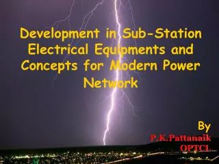
Development in Sub-Station Electrical Equipments and Concepts for Modern Power Network. By P.K.Pattanaik OPTCL. Introduction. Catch word :- ( PQRS ) P ower with Q uality, R eliability and S ecurity The rapid development of power systems – need of the Hour.

E N D
Development in Sub-Station Electrical Equipments and Concepts for Modern Power Network By P.K.Pattanaik OPTCL
Introduction Catch word :- (PQRS) Power with Quality, Reliability and Security • The rapid development of power systems – need of the Hour. • Necessity of developed electrical equipments with • Innovative idea/ Concepts
Surge Arrestor / Lightning Arrestor • Modern surge arrestors :- • Metal Oxide Varistor (MOV)- ZnO2 Blocks with grain of 10μm dia. • Confirms IEC 60099-4 / IS 3070 with safety Vent and LCM ( Leakage Current Monitor) • Metal Oxide Varistor (MOV) is highly nonlinear in nature, which has sharply kinked voltage-current characteristics.
LOCKING OF ISOLATOR IN END POSITION Isolators/ Dis-connector • Modern Isolators :- • Single Break motorized type – Proper Gripping due to dragging each other. • One contact – provides 100% confirmed status. • Interlock scheme from Numerical Micro-processor Relay. • Operates on OFF load or EQUI-POTENTIAL Concept.
Insulator Stacks Hydrophobicity • Modern Insulators :- Composite Insulators • Long Life / Suitable for polluted environment / Light weight • Unique self cleaning property/ Long term surface hydrophobic • Ease for installation
Dead Tank CT Live Tank CT Instrument Transformer ( CT) • Modern CTs :- • Live Tank CTs (Better and less Insulation, less conductor Path and cheaper in cost.) • Optic Fiber CTs • (No current Path , No magnetic effect). • 3.Polycrete CTs / SF6 Filled CTs( Better insulation , Less maintenance)
OPTIC FIBRE CT OPTIC FIBRE PT OPTIC FIBRE CT
Instrument Transformer ( IVT/ CVT ) MVT CVT OPTIC FIBRE CT
Combined CT-PT • Less installation space • Cheaper in Cost • Low Weight with minimum Oil. • Less Installation Cost • More Stable both Mechanical and electrical.
Switch Gear/ Circuit Breaker VCB • UP TO 36 KV( VCB ) • Quick Restoring of Dielectric strength of Gap • Short gap needs lesser Control Mechanism • Low Weight • 72 KV to 800 KV ( SF6 Filled Spring Mechanism) • SF6 (electronegative in nature with high quenching property and high dielectric strength • Spring- Spring mechanism takes less space and simple mechanism . *CIGRE 1994:-Tech Report 83:- CIGRE analyzing worldwide Circuit Breaker advises the use of spring operating mechanism in order to ensure the highest reliability.
Switch Gear/ Circuit Breaker 800 KV SF6 LIVE TANK 400 KV SF6 Gas OPERATED MECHANISM
Switch Gear/ Circuit Breaker CB with Composite Insulator CB with PIR and Graded Capacitor
Transformers • MODERN TRENDS for Transformer Design • Enamel Coated conductor for better insulation in winding • Epoxy Bonded Cable for reduction of Eddy Loss • Continuously transposed cable for enhancement of induction voltage and elimination of equalizing current. • Step lap Core joints for reduction of Flux Leakage • Use of HIB material, Laser Irradiation and Plasma Irradiation method and Amorphous core for reduction of Eddy loss • Use of Flux shunts, flux rejecter and use of non- magnetic material for control of leakage flux. • SF6 Insulated Transformer. • HTS ( High Temperature Super Conductor ) material for increase efficiency. • Transformer Oil with Multiple barrier for increase of breakdown strength of the oil . • Fuzzy Logic Control on OLTC
MODERN TRENDS for Transformer MANAGEMENT System • Use of SINGLE RELAY “ TRANSFORMER MANAGEMENT RELAY • Protection and Control Scheme • Metering Scheme • Monitoring Scheme
Grid SUB-STATION • GIS ( GAS INSULATED SYETM ) • Expansion / up-rating of existing s/s • Non availability of sufficient space for s/s • Difficult climatic and seismic conditions at site • Urban site (high rise bldg.) • High altitudes • Limitations of AIS
GIS ASSEMBLY 1. Bus bar2. Circuit Breaker3. Disconnector 4. Earthing switch 5. Current transformer 6. Voltage transformer 7. Feeder Disconnector 8. Feeder Earthing switch 9. Lightning / Surge Arrester 10. Cable termination 11. Control Panel.
GIS Bay Single Line Diagram
PROTECTION DEVICES • Numerical Relays • Facility of recording, storing and retrieval of data • Well Communicated for quick and reliable action. • Event Logger/DR/ Fault Recorder • Data Recording and applications for corrective decision. • Well Communicated
Fault Recording SCADA RTU Event Recording ABB ABB 225kV LIGNE ABOBO 1 225kV LIGNE ABOBO 1 =D04+R01 =D04+R01 Bay Control Bay Protection Busbar Protection ABB ABB ABB ABB 225kV LIGNE ABOBO 1 =D04+R01 225kV LIGNE ABOBO 1 225kV LIGNE ABOBO 1 225kV LIGNE ABOBO 1 =D04+R01 =D04+R01 =D04+R01 ABB 225kV LIGNE ABOBO 1 =D04+R01 125VDC Distributuion Battery A 125VDC Distributuion Battery B 125VDC Distributuion Battery A 125VDC Distributuion Battery A 125VDC Distributuion Battery A 125VDC Distributuion Battery B 125VDC Distributuion Battery B 125VDC Distributuion Battery B ABB ABB ABB ABB ABB ABB ABB REL316*4 ABB Network Partner =W1 =W1 =W2 =W2 125VDC Distributuion Battery A 125VDC Distributuion Battery B 1 9 1 -Q1 -Q1 -Q2 -Q2 2 10 3 11 SEL SEL SEL SEL 4 12 5 13 6 14 RTU 200 RTU 200 RTU 200 IN 1 IN 1 IN 1 IN 2 IN 2 IN 2 IN 3 IN 3 IN 3 IN 4 IN 4 IN 4 IN 5 IN 5 IN 5 IN 6 IN 6 IN 6 IN 7 IN 7 IN 7 IN 8 IN 8 IN 8 OUT OUT OUT 7 15 8 16 Indactic 650 Indactic 650 Indactic 650 Indactic 650 -Q0 -Q0 SEL SEL TESTE LAMPE TESTE LAMPE ON/OFF ON/OFF ON/OFF OUVRIR OUVRIR FERMER FERMER ABB ABB DISTANCE DISTANCE ESC ESC EXE EXE LOC LOC BAY CONTROL RELAY REC316*4 -Q1 -Q2 =W1 =W2 -Q1 1 9 2 10 3 11 4 12 5 13 FERMER 6 14 7 15 8 16 Veriosn 4.2b LOCAL CONTROL METERING c c ABB REL316*4 ABB Network Partner 1 9 2 10 3 11 3 4 12 5 13 6 14 7 15 8 16 8 LINE PROTECTION RELAY REL316*4 ABB REB500 ABB Network Partner BUSBAR PROTECTION REB500 -Q0 -Q9 -Q8 Conventional Control & Protection Station Level For each function a dedicated device and separate kiosks Extensive station wide cabling Local Control Bay Level Extensive bay cabling GIS or AIS Switchgear Process Level
Control/Protection Cubicles MicroSCADA Fällanden =AD17-KB2 Steuerung / Schutz 220VDC SPANNUNG SYS 1 220VDC SPANNUNG SYS 2 Interbaybus Star coupler Fällanden =AD17-KB2 Steuerung / Schutz Feldsteuergerät REC216 mit Messung und Synchrocheck 220V DC / 230V AC LEISTUNGSSCHALTER LS HYDRAULIK LS HYDRAULIK ANTRIEBSMODULE ACHTUNG ! SCHUTZ-STEUERSPG. SF - GAS PUMPE FEDERSPANNUNG AUSGANGSRELAIS SCHALTHANDLUNG I 0 - SPANNUNG NACHFÜLLEN ZU VIELE ANLÄUFE STÖRUNG (OCO) STÖRUNG VERRIEGELT 24V DC LS HYDRAULIK LEISTUNGSSCHALTER LEISTUNGSSCHALTER/ SPANNUNGSWANDLER SCHALTHANDLUNG PROZESS INTERFACE PUMPENLAUFZEIT EINSCHALTKREIS TRENNER/ERDER SICHERUNGSÜBERW. UNVOLLSTÄNDIG 0 SPG. STÖRUNG ÜBERSCHRITTEN BLOCKIERT (CO) POSITION GESTÖRT ANGESPROCHEN LS AUSLÖSEKREIS- LS AUSLÖSEKREIS- LEISTUNGSSCHALTER LEISTUNGSSCHALTER TRENNER/ERDER ÜBERWACHNUNG 1 ÜBERWACHNUNG 2 AUSSCHALTKREIS PHASEN-DISKREPANZ MOTORSCHUTZ ANGESPROCHEN ANGESPROCHEN BLOCKIERT (O) AUSGELÖST ANGESPROCHEN VERRIEGELUNG LEITUNGS- LEITUNGS- LEITUNGS- SAMMELSCHIENEN SAMMELSCHIENEN-/ HAUPTSCHUTZ HAUPTSCHUTZ RESERVESCHUTZ SCHUTZGERÄT SCHALTERVERSAGER STÖRUNG AUSGELÖST AUSGELÖST STÖRUNG -SCHUTZ AUSGELÖST SAMMELALARME FELDSTEUERGERÄT BETRIEBSZUSTAND SIGNAL-/ALARMANLAGE RELAISHAUS 2 FERN ALARM HORN LAMPEN ZUSTAND RELAISHAUS 3 LOKAL / NORMAL QUIT QUIT TEST EIN RELAISHAUS 4 LOKAL / DIREKT =AD17 FÄLLANDEN SAMMELSCHIENENSPANNUNG 0 100 200 30 2a 0 0 100 200 30 1a 0 -JA1 -JA2 d g i t a l ( L2121 ) ( L2122 ) WIRKLEISTUNG -480 +480 BLINDLEISTUNG -240 +240 R FEDER / SF PUMPEN -JA4 RÜCK- S EIN-BLOCKIERT ( L2111 ) STELLEN T AUS-BLOCKIERT STROM 0 500 1000 1500 R KOMBIWANDLER -JF1 R WANDLERALARM 0 500 1000 1500 S ( L2151 ) S GASSCHUTZ ( L2141 ) T RER111 ABB 0 500 1000 1500 Power Automation AG T LEITUNGSHAUPTSCHUTZ REL316*4 PRÜFSTECKER -JA5 ( L2126 ) SPANNUNG 100 30 0 200 0 I I I Reset MESSANWAHL 0 0 0 500SCM 500SCM 500SCM 500SCM 500SCM 0 R-S R-N AUS d i g i t a l S-T S-N STUFENVERL. WE-BLOCK SCHUTZ EIN/AUS 01 01 01 01 01 -JA6 Tx1 Tx1 Tx1 Tx1 Tx1 T-R T-N ( L2136 ) ANTRIEBSSTEUERUNG RÜCK- AUS- EIN AUS STELLEN FÜHREN Rx1 Rx1 Rx1 Rx1 Rx1 NORMAL FERN DIREKT LOKAL Tx2 Tx2 Tx2 Tx2 Tx2 Rx2 Rx2 Rx2 Rx2 Rx2 -Q2 -Q1 Tx3 Tx3 Tx3 Tx3 Tx3 Rx3 Rx3 Rx3 Rx3 Rx3 SAMMELSCHIENENSCHUTZ REB500 RESERVESCHUTZ I -X1 0 AUS SYNCHRONISIERUNG HAND SCHUTZ EIN/AUS COM581 ABB Power Automation AG 2 x 220/24V DC/DC SPANNUNGSVERSORGUNG NCC / RCC Communication Converter -Q0 C Control Cubicle Relays for control / logic Transducers, Meters Switches, Lamps Annunciators, Terminals Feeder Marshalling -Q9 Mimic control board -Q8 Marshalling Protection Cubicle Interface Fault Recorder Substitution of Conventional Technology
MicroSCADA Interbaybus Star coupler Process bus Star coupler d g i t a l -Q2 -Q1 RER111 RER111 ABB ABB Power Automation AG Power Automation AG 500SCM 500SCM 500SCM 500SCM 500SCM 500SCM 500SCM 500SCM 500SCM 500SCM d i g i t a l 01 01 01 01 01 01 01 01 01 01 Tx1 Tx1 Tx1 Tx1 Tx1 Tx1 Tx1 Tx1 Tx1 Tx1 PISA Rx1 Rx1 Rx1 Rx1 Rx1 Rx1 Rx1 Rx1 Rx1 Rx1 Tx2 Tx2 Tx2 Tx2 Tx2 Tx2 Tx2 Tx2 Tx2 Tx2 Rx2 Rx2 Rx2 Rx2 Rx2 Rx2 Rx2 Rx2 Rx2 Rx2 -Q2 -Q1 Tx3 Tx3 Tx3 Tx3 Tx3 Tx3 Tx3 Tx3 Tx3 Tx3 Rx3 Rx3 Rx3 Rx3 Rx3 Rx3 Rx3 Rx3 Rx3 Rx3 -Q51 COM581 ABB Power Automation AG NCC / RCC Communication Converter -Q0 C -Q0 PISA A Feeder Marshalling -T1 PISA -Q9 A PISA B -Q8 M M M ? LOCAL SET REMOTE OPERATION -Q9 -Q8 Implementation of Intelligent Technology Intelligent Primary Equipment t Drive control & monitoring circuitry i i t l Process Bus Conventional bay cabling is substituted Sampling AD-Conversion Signal Processing Signal Filtering
New Technologies to be adopted • Enhancing the capacity of existing system • Asset management • Enhancement of Thermal capacity • Up gradation to higher voltage line • Series Compensation (Fixed as well as TCSC) • Static Var Compensator(SVC) • State-of-the-Art maintenance techniques being practiced • Hot Line Helicopter supervision • Thermo-Vision Camera
New Technologies to be adopted … Other Technologies • High Temp endurance conductor for increased Loading • Multi-conductor Bundle line • Satellite imagery for Transmission Line Survey (Survey through GIS/Digital Terrain Model/Airborne Laser Terrain Mapping (ALTM)) • Tall & Multi ckt Towers to avoid deforestation and protection of wild life • Compact Tower / Pole Tower to reduce Right Of Way • Substation Compaction to reduce land requirement • Automation of Sub-stations • Unified Load Dispatch & Communication centers at all region integrated with State-of-the-Art SCADA/EMS
Future Technologies - Intelligent Grid • Need for infusion of Intelligence in the Grid for : • Knowing the state of the Grid • Predict the catastrophic situation in advance • Take corrective actions accordingly so as to protect the grid • Features of Intelligent Grid • adoptive islanding, • self-healing • demand/generation management etc. • To Accomplish, need for Wide Area Monitoring System (WAMS). • To gather and processing the data from any number of GPS-synchronized phasor measurement units (PMUs) along with a system monitoring centre and take corrective action through advance software and control system
ADVANCE CONCEPTS • LADR ( Load Accessed Directional Relay) • Super grid (Hybrid transmission system supported 1200kV, 765kV, 400kV UHVAC & 800kV, 500kV HVDC system). • Intelligent Power system protection & control • WAMS ( Wide Area Monitoring Systems) • FACTS devices, and controller interaction • OPGW (Optical Fiber Ground Wire) • Congestion Management and control • SMART Grid Technology
LADR SCHEME ON POWER CONTROL • Programmed on the basis of load availability to avoid system disturbance. • Auto changes the settings and issues command either for load shedding or generation shedding. • Allows extra load flow on the flexible feeders for the allowable allotted time span. • Programmable for dI/dt during system disturbance to decide the logical tripping. • Simulates the target loads and generator loads for preparation of logical tripping scheme.
Maintaining Uniform power flow through 1200kV UHVAC Super grid Through Control of Power Flow on HVDC sections 800kV HVDC 1200kV UHVAC SYSTEM 765kV EHVAC SYSTEM ~ 400kV EHVAC SYSTEM ~ 220kV/132kV SYSTEM
CONCLUSION Need of the Hour to accept the Modern Up dated Technology “If we don’t strive for change, then change will drive us away.”