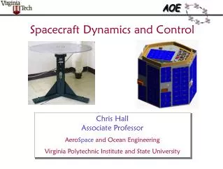
Spacecraft Dynamics
Spacecraft Dynamics . with your host…. Dr. Hy, the rocket scientist guy. AERO 426, Lecture #5 Spacecraft Dynamics- Questions Addressed. How can we tell where our spacecraft is ?. What are some simple ways to estimate the motion of spacecraft in the vicinity of a NEA?.

Spacecraft Dynamics
E N D
Presentation Transcript
Spacecraft Dynamics with your host…. Dr. Hy, the rocket scientist guy
AERO 426, Lecture #5 Spacecraft Dynamics- Questions Addressed How can we tell where our spacecraft is ? What are some simple ways to estimate the motion of spacecraft in the vicinity of a NEA? How can we plan space trajectories and estimate propulsion system requirements? Regarding available and future launch systems, what are the implications for cost versus payload size, weight, etc.?
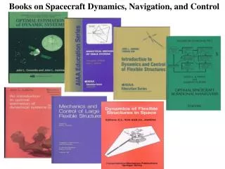
Suggested reading: L&W, Chap.5 intro or P&M, Sect. 3.3 (coordinate systems), L&W, Sect. 6.1.1 - 6.1.3 or P&M, Sect. 3.6 (Keplerian orbits), L&W, Sect. 6.3 (orbit maneuvering), L&W, Sect. 17.2 or P&M, Sect. 4.2.1 and 4.3 (rocket propulsion and motion), L&W, Sect. 17.3 (types of rockets), L&W, Sect. 18.2 (launch system data)
Jorbit ~ RESXMEVE ~ Const Orbit plane is fixed Jspin~ Constant RES VE What’s our coordinates? Use Nature’s Gyros! So, we have two axes that are fixed: The perpendicular to the orbit plane and the axis of rotation of the Earth (which actually nutates once every 26,000 years)
Y-axis Ecliptic Pole, Z-axis Orbit Plane Actually, in the Ecliptic coordinate system;We use the normal to the orbit plane (called theEcliptic Pole) as the Z-axis In the position of the vernal equinox, the rotation axis vector is perpendicular to the Sun-Earth vector and Northern Hemisphere spring commences X-axis
Locating Events in Time The Julian day or Julian day number (JDN) is the integer number of days that have elapsed since the initial epoch defined as noon Universal Time (UT) Monday, January 1, 4713 BC in the Julian calendar. The Julian date (JD) is a continuous count of days and fractions elapsed since the same initial epoch. The integral part gives the Julian day number. The fractional part gives the time of day since noon UT as a decimal fraction of one day with 0.5 representing midnight UT. Example: A Julian date of 2454115.05486 means that the date and Universal Time is Sunday 14 January 2007 at 13:18:59.9. The decimal parts of a Julian date: 0.1 = 2.4 hours or 144 minutes or 8640 seconds 0.01 = 0.24 hours or 14.4 minutes or 864 seconds 0.001 = 0.024 hours or 1.44 minutes or 86.4 seconds 0.0001 = 0.0024 hours or 0.144 minutes or 8.64 seconds 0.00001 = 0.00024 hours or 0.0144 minutes or 0.864 seconds. The Julian day system was introduced by astronomers to provide a single system of dates that could be used when working with different calendars. Also, the time separation between two events can be determined with simple subtraction. To make conversions, several handy web-sites are available; e.g., http://aa.usno.navy.mil/cgi-bin/aa_jdconv.pl
Orbital Dynamics - Made Simple Most of the time (with many important exceptions) spacecraft orbital dynamics involves bodies that are either (1) very, very small relative to inter-body distances, or (2) are nearly spherically symmetric -- then: Bodies behave (attract and are attracted) as if they are point masses. Motion can be described by keeping track of the centers of mass. Also, most of the time (with many important exceptions) spacecraft orbital dynamics is a two-body problem (the s/c and the Earth, or the s/c and the sun, or, etc.) - so we have two gravitationally attracting point masses, and: Both bodies move in a plane (the same plane) Both trace out conic sections with one focus at thetotal center of mass. Each body moves periodically on its conic section, tracing and retracing the same curve forever.
Finally, most of the time (with many important exceptions), one of the bodies is much more massive than the other ( the Earth versus a s/c, or the sun versus the Earth, etc.). Then in addition to the above: The smaller body moves on a conic section witha focus on the larger body's center of mass, which is also approximatelythe total center of mass. The motion of the smaller body does notdependon its mass. The smaller body's motion dependson the gravitational constant, G, and the larger body's mass only through the combination: = "The Gravitational Parameter" = GM G = 6.673 x 10⁻¹¹ m3/ kg-s2 M = Mass of the larger body
Euler Angle Description of the Orbit Plane Orbit Plane Equitorial Ecliptic plane f Periapsis
hyperbola v0 = vf d d(v0)2/m Orbital Dynamics - Briefly Summarized d Parabola: vmax = (2)1/2 =vescape E = 0 parabola vf v0 ellipse rmax hyperbola Hyperbola: vmax = v0 [ 1 + (1 + 2)1/2] / , rmin = dv0 / vmax sin() = /(1 + 2 )1/2 E 0 Ellipse: rmax = rmin (vmax)2 / (2 - (vmax)2) 0 E E0 circle For all orbits: e =m / rmin E = v2/2 - m / r = / 2a a = (rmax+ rmin)/ 2 Circle: v = vmax = 1/2 E = E0 = - /2 rmin For bound orbits: vmax
Location of a Body in its Orbit as a Function of Time b r F2 E f a F1 ae
Asteroid Sun Earth Getting from Earth to a NEA - Patched Conics Method When S/C crosses asteroid’s activity sphere boundary, subtract the asteroid’s velocity relative to the sun.This gives initial conditions for the asteroid-dominated portion of the rendezvous Sphere of Influence of the asteroid: S/C acceleration due to asteroid > Perturbing acceleration due to the Earth. SI radius given by: RSI RA-E (Masteroid /MEarth)2/5 (Masteroid = 4.6X10¹⁰ kg MEarth=5.9737X1024 kg ) (Masteroid /MEarth)2/5= 2.2626X10⁻⁶ Within SI and ref. frame moving with the asteroid, S/C approx. interacts only with the asteroid. When outside the Earth’s activity sphere, calculate only the S/C orbit around the Sun. (which follows a conic section).
V (km/s) Topography Mars Sun Low Mars orbit 4.1 Phobos 0.5 0.9 Phobos transfer 0.3 Deimos transfer 0.7 0.2 30 Mars C3 Deimos 0.9 Mars transfer 0.6 Optional Aerobrake Earth C3 0.7 Orbital location GTO 0.7 2.5 1.6 1.6 GEO 3.8 1.7 LEO L4/5 4.1 9.3 - 10 Lunar orbit 0.7 Moon Earth 1.6
Planar Circular Restricted 3-Body Problem(PCR3BP) • “Restricted” = Gravitational field is determined by two massive bodies (The “primaries”). The third body is too small to affect the primaries. • “Circular” = The primaries are in circular orbits about the total center of mass • “Planar” = All three bodies move in the same plane. • Normalized Units: • Unit of mass = m1+m2 • Unit of length = constant separation between m1and m2 • Unit of time: Orbital period of m1and m2 is 2 (G = 1) • The only parameter in the system is = m1/(m1+m2)
Unit of distance: L = distance between m1 and m2 (km)Unit of Velocity: V = orbital velocity of m2 (km/s)Unit of time = orbital period of the primaries (s)
Patched 3-Body Method: LL1 to EL2 in 40 days with a single 14m/s V
Rotational Dynamics of Axisymmetric Rigid Bodies Z axis inertia = C z x y x and y axes moment of inertia = A
Rotational Dynamics of Axisymmetric Rigid Bodies z x y This does not happen when C >A
Combustion Chamber F Ve Propulsion Systems - Key Parameters Oxidizer Fuel F Thrust Ve (dm/dt) Ve =exhaust velocity dm/dt = propellant and oxidizer mass flow rate dm/dt IspSpecific Impulse = F / (g dm/dt) -- depends on propulsion type Nozzle (liquid, solid, chemical, electric, etc.) , energetics of chemical reactions, etc.
Key Propulsion Parameters Related to Important Trajectory Parameters Suppose we have a thruster burn event with constant thrust (maybe to inject the spacecraft into a higher orbit, etc.). Define: m0 Total mass of vehicle before burn event mp Mass of propellant (& oxidizer) used in burn event
Trajectory Parameters/ Propulsion System Relations: ΔV = Total change in vehicle speed = g Isp ln (m0/( m0 - mp)) Δt = Time elapsed during burn event = g Isp mp/ F • Trajectory Requirements Needed DV and Dt • Use above relations to estimate total mass of propellant • Select propulsion system (F & Isp) and design trajectory to minimize total propulsion system • mass
Determining Propulsion System Requirements - For Transport of S/C to its Mission Station Lay out the entire trajectory and itemize the DV maneuvers. Start from the last DV maneuver and use the DV/ mp equation to determine mp (where here, m0- mp = the final S/C mass), for several values of Isp From considerations of the Dt desired, or other practical constraints, determine any thrust level requirements. Now narrow the selection of propulsion systems to those consistent with required thrust levels.
Now, carry out the above process for all the V maneuvers, working back along the trajectory. Get a range of values for mp and F. Finally, obtain the total propulsion system masses corresponding to different propulsion system options. Select option with smallest cost and/or launch weight.
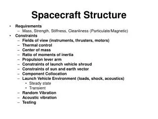
Launch Systems • Key Parameters are: • Mass of payload that can be injected into LEO or GTO or GEO • Fairing diameter and length
Good Luck With Your Mission! and watch out for those irate Romulans!