Download
1 / 35
1.87k likes | 3.18k Views
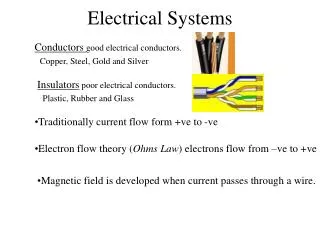
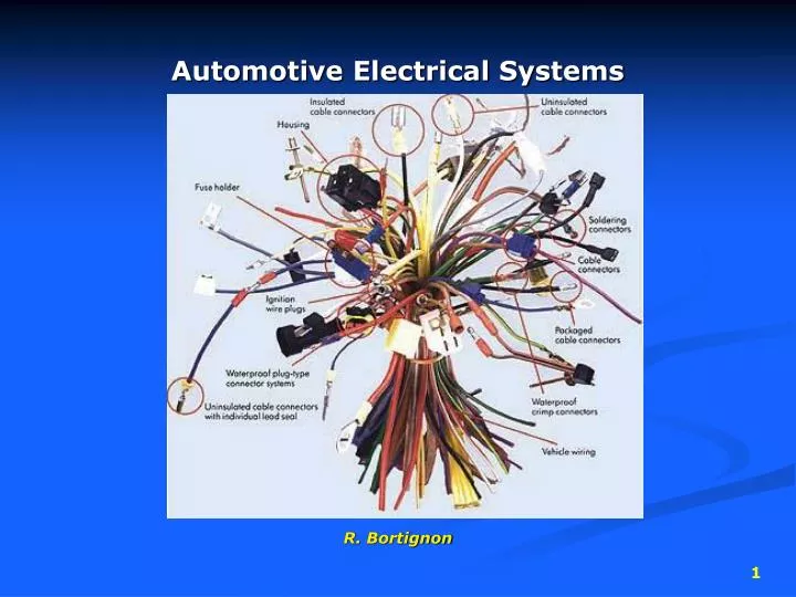
Automotive Electrical Systems. R. Bortignon. Electrical Circuits. Contain 4 main parts… 1. Power source battery alternator. Load. 2. The load in a circuit is the part that does the work load will always have some resistance this resistance can be measured. Control.

E N D
Automotive Electrical Systems R. Bortignon
Electrical Circuits Contain 4 main parts… 1. Power source • battery • alternator
Load 2. Theloadin a circuit is the part that does thework • load will always have some resistance • this resistance can be measured
Control 3. The control is what turns the load on or off… • opens & closes the circuit • may be installed on the ground side or the power side of circuit
Path 4. The path are the wires that connect the battery & alternator to the control and load devices in a circuit • frame/body of the vehicle is a path for the ground circuit
Circuit Protection • to protect the vehicle’s electrical system from excessive current flow, fuses are used • fuses open the circuit if current (amperage) levels exceed a predetermined level
Types of Fuses • cartridge fuses • blade type fuses • mini size • standard size • maxi size • mega fuse • ceramic disc fuses • see info on next slide • replace fuses with correct amperage rating!!!
Positive Temperature Coefficient Fuses • PTC fuse technology utilizes a polymer-based material to protect electrical circuits from excessive current. • During normal operation, numerous carbon paths within the polymer allow the device to conduct electricity. • As current through the PTC fuse reaches its rated threshold, the polymer material begins to heat causing the polymer to expand. • The resulting expansion breaks the carbon chains to reduce the current through the circuit to a small leakage current. • The increased resistance in this resettable fuse works to protect circuitry by limiting potentially damaging current. • When the fault (over-current) is removed from the circuit, the PTC fuse will reset itself thereby allowing current to flow through the circuit again.
Fuse Panel Locations • can be located… • under left side of instrument panel • in the engine compartment • many vehicles have fuse panels in both locations
Fusible Links • special wire that breaks & opens a circuit when overloaded • insulation bubbles, melts & opens to expose wire • usually connected near the battery & feeds the fuse box(es) • must be replaced with correct rating • not all vehicles use fusible links • modern vehicles use maxi fuses instead of fusible links
Circuit Breakers • some circuits such as power windows & power seats use circuit breakers • circuit breakers reset themselves when current levels are back to normal • (do not need to be replaced like fuses)
Testing Fuses • 1) test with an ohmmeter set on the low scale • should have low/no resistance • be careful checking fuses visually
Testing Fuses • 2) test with a test light • the key may have to be in the on position • the control/switch for the circuit may have to be on • test light should light up on both sides of the fuse • if only one side lights up – fuse is open • if neither side lights up – power is not reaching the fuse 3 1 2
Relays • use a low current signal to activate a high current circuit • relay coil draws 150mA • contacts can conduct 30-50amps
Electrical Faults – High Resistance • circuit may not work at all • circuit may be dim or work poorly / slowly
Electrical Faults – Low Resistance • the load’s resistance is partially or totally bypassed • often referred to as a short • causes higher than normal current flow • usually causes fuse to open the circuit frayed wire/bare insulation
Light Bulbs • bulbs can be single or double filament • double filament = brake light & park light • note the offset indexing pins & 2 contacts • newer style bulbs do not require indexing
Testing Bulbs • often “blown” bulbs are easily seen during a visual inspection • sometimes a DVOM will verify the problem • use low resistance setting • polarity doesn’t matter • most bulbs will be ≈ 3Ω to 10Ω • you are looking for… • shorts (low/no Ω) • opens (high Ω)
Testing Headlamps • older style sealed beams • newer halogen, xenon bulbs • do not touch the quartz when replacing these! • 1 connector is for ground – check for continuity to ground • 2nd connector is for hi beam – check for voltage • 3rd connector is low beam – check for voltage
Turn Signals • blinking function of the turn signals is controlled by turn signal flasher • may have 1 that controls turn signals & 4 way flasher • or 2 separate units • located in fuse box or under the left side of the dash • if one side flashes abnormally fast – check for faulty bulb on that side of the vehicle • if both sides flash incorrectly, the flasher unit may be faulty
Reading Wiring Diagrams • wire colors – jacket color followed by stripe color • connectors – identification numbers • usually +side of the circuit up top & ground at the bottom • ground number & locations
Using Component Location Function • component locator can be used to find connectors, relays, grounds, modules etc. • access electrical, then component location in Mitchell
Starter Circuit • terminal “B” (battery) is live at all times • terminal “S” (start) feeds power only when the key is in the starting position • “S” terminal will have a neutral safety switch in series for an automatic transmission equipped car • “S” terminal can also have a clutch safety switch in series for a manual transmission equipped car • “S” terminal may have remote starter switch or alarm disabling feature tied into it • terminal “M” (motor) has power during cranking only M B S
Starter Solenoid • serves same purpose as a relay • is usually mounted directly on the starter motor • on Fords, it is mounted remotely on the inner fender
Voltage Drop Test determines if too much voltage is being lost to poor connections voltmeter is set to low voltage scale (0-2v) meter leads are placed across a connection (circuit must be turned on during testing) there should not be more than .1v loss per connection both the positive and ground circuits can be tested this way
Hey Mr. B can I install… the next 5 slides are helpful when adding electrical accessories to a vehicle
Adding Accessories • you and your students need to carefully consider what’s needed when adding amplifiers, driving lights etc. • add a relay to an existing circuit so you don’t overload the original circuit
Adding Fuses to Add-on Accessories • when adding additional equipment, add a relay to power the circuit • calculate the required fuse amperage • eg: 2 fog lights 4Ω each • amperage = 12 volts ÷ 4Ω = 3 amps through each light • 3 amps X 2 lights = 6 amps total • 6 amps flowing through circuit • multiply this by 1.5 to allow for any voltage surges • 6 amps X 1.5 = install a 9 amp fuse
Hey Mr. B, do you have any wire? determining wire gauge size for add-on circuits… • use a wire gauge table • always better to use a larger gauge size than is required
Wiring Repair Tips • use grommets & loom to protect wires against abrasion • crimp & solder, then heat shrink • don’t rely on crimp only • on air bag systems & circuits to/from computer modules, follow manufacturer’s specific repair instructions
ISO 4 pin & 5 pin relay pin-outs…for your reference 4 pin relay 5 pin relay