Nonlinear behavior and intermodulation suppression in a TWT amplifier
290 likes | 483 Views
Nonlinear behavior and intermodulation suppression in a TWT amplifier. Aarti Singh University of Wisconsin - Madison. Acknowledgments: J. Wöhlbier, J. Scharer and J. Booske. Outline. Characterization of Nonlinearity in terms of distortion products (Identify harmonics and intermods).

Nonlinear behavior and intermodulation suppression in a TWT amplifier
E N D
Presentation Transcript
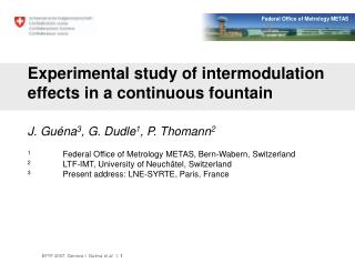
Nonlinear behavior and intermodulationsuppression in a TWT amplifier Aarti Singh University of Wisconsin - Madison Acknowledgments: J. Wöhlbier, J. Scharer and J. Booske
Outline • Characterization of Nonlinearity in terms of distortion products (Identify harmonics and intermods). • Nonlinear behavior description of a TWT amplifier. • Why suppress intermods? • Intermodulation suppression techniques and Experimental results.
f f 2f 3f … f1 f2 f1 f2 2f1 2f2 Nonlinear distortions Nonlinear system Single-tone case: Generation of harmonics Nonlinear system Multi-tone case: Generation of IMPs (intermodulation products)
f1 f2 f1+f2 2f1 2f2 Nonlinear distortions (contd..) Multi-tone case: Generation of IMPs (intermodulation products) 2f1-f2 2f2-f1 3f1-f2 3f2-f1 3f1-2f2 3f2-2f1 … … … … ~2f ~f m+n mf1±nf2 Order relevant freqs Order relevant freqs 1f1, f2 2 2f1, 2f2, f1+f2 4 3f2-f1, 3f1-f2 32f2-f1, 2f1-f2 (IM3s) 5 3f2-2f1, 3f1-2f2 (IM5s)
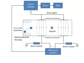
TWT amplifier operation Helix (slow-wave structure) collector e- beam RF output RF input Circuit Voltage Electron bunches Saturation Bunch formation Exponential gain
Nonlinear behavior characterization DF Pout DΦ(r) A(r) Pin Pin r r AM-AM curve AM-PM curve
A(r) r DΦ(r) r Nonlinear behavior characterization Odd-order terms Even-order terms fc+fm fc-fm Vin(f) Vout(f) fc-fm fc+fm A(r) = acos(mt) fc-3fm fc+3fm (r) = 0+a2cos2(mt) fc-5fm fc+5fm
Circuit voltage Beam current z=L z=0 z=L z=0 Axial position Axial position Nonlinear behavior characterization (contd…) Harmonics arise due to non-sinusoidal e- bunching, not only at saturation but also in the “linear” gain region.
1 2 … N bandwidth bandwidth 1 2 … N time time TDMA FDMA Motivation for Multi-tone analysis • High data rate communications Data rate bandwidth N simultaneous users -efficient use of available bandwidth. • Covert communications Spread Spectrum Techniques (CDMA or pseudo-noise signaling)
~f ~f ~f ~f CHANNEL SPACING CHANNEL A CHANNEL C CHANNEL B Why suppress Intermods ? Spectral regrowth around the fundamentals leads to: • In-band distortions • Adjacent channel interference • Limitation on Power efficiency – need back off
Channel BW f OFDM spectra Why suppress Intermods? (contd…) Newer modulation schemes aggravate these problems: • The closer the carrier spacing, the more pronounced is the effect of the IMPs. Single tone 2GHz • Saturation occurs earlier with multiple carriers – more power limitations. Two tone 2GHz • High PAR (Peak to Average Ratio) of modulation schemes like OFDM and CDMA requires more OBO (Output Back Off).
f1 f2 IM3- IM3+ IM5- IM5+ … … Research Objective • To investigate intermodulation suppression techniques that achieve: - maximum suppression for IM3 • reduction of higher (5th, 7th) order intermods • or have no effect on them - easy implementation
f1 f1 f1 f2 f2 f2 f1 f2 IM3+ IM3+ IM3+ IM3- IM3- IM3- 2f2 f1 f2 IM3+ f1 f2 2f2 IM3+ Techniques for IM3 suppression Input spectra Output spectra • Harmonic injection • IM3 injection • Two frequency (harmonic + IM3) injection
Mechanism of IM3 suppression by injection Impressed and Nonlinear modes have different growth rates and wavelengths.
Mechanism of IM3 suppression by injection Impressed and Nonlinear modes have different growth rates and wavelengths. Sum nonlinear product impressed
Mechanism of IM3 suppression by injection Normalized voltage Axial distance Suppression occurs only at the output of the tube.
f2 2.00 GHz f1 1.95 GHz 2f2 (4.00GHz) x2 Variable Attenuator Phase shifter Gated Spectrum Analyzer Semi Rigid Coax Solid State Amplifiers Isolator Combiners TWT Experimental Set-up Variable Attenuator
Experimental TWT XWING (eXperimental Wisconsin Northop Grumman) TWT Broadband (1.5-6 GHz gain bandwidth) Maximum gain 30dB at ~ 4 GHz RF sensor array along helix
optimum injection without injection Harmonic injection f1 = 1.90 GHz 2f2-f1 = 2(1.95)-1.90 = 2.00 GHz (nonlinear product) f2 = 1.95 GHz 2f2-f1 =3.90-1.90 = 2.00 GHz (impressed product) 2f2 = 3.90 GHz D IM3 -32.4 dB D IM3 -29.5 dB
Harmonic injection Sensitivity (18 dBm/tone) IM3 Power w/o inj 13.53 dBm Relative Injected Harmonic Phase (degrees) Relative Injected Harmonic Amplitude (dBm)
optimum injection without injection IM3 injection f1 = 1.90 GHz 2f2-f1 = 2(1.95)-1.90 = 2.00 GHz (nonlinear product) f2 = 1.95 GHz 2f2-f1 =2.00 GHz (impressed product) 2f2-f1 = 2.00 GHz D IM3 -30.0 dB D IM3 -26.6 dB
Two Frequency (Harmonic+IM3) injection Voltage Phasor diagram at z=L Concept: IM3 voltage components at output: Resultant IM3 • Naturally produced IM3 • IM3 due to injected harmonic Injected IM3 IM3 due to injected harmonic • Injected IM3 Naturally produced IM3 Experimental challenge: Keeping phase fixed as amplitude is varied.
Two Frequency (Harmonic+IM3) injection D IM3 30.7 dB
Spatial evolution of IM3 with optimum injection (Harmonic + IM3)
Summary • The nonlinear behavior of TWTs gives rise to harmonics and intermods. • Minimization of these nonlinear products is important for reliable • communications. • IM3 suppression techniques were investigated that employ injecting an • amplitude and phase adjusted harmonic, IM3 or simultaneous injection • of both with only amplitude adjustment. • Strong suppression of ~26-32 dB was measured. • It was observed that harmonic injection may lead to reduction in IM5s • and harmonics too, while IM3 injection may enhance these. The two • amplitude (harmonic+IM3) suppression technique offers possibly better • implementation issues. • Understanding the theoretical details underlying the nonlinear behavior is a topic of current research. Ref - M. Wirth, A. Singh, J. Scharer and J. Booske, "Third-Order Intermodulation Reduction by Harmonic Injection in a TWT Amplifier", IEEE Trans. on Electron Devices, pp. 1082-84, vol. 49, No. 6, June 2002.