Download
1 / 24
240 likes | 447 Views
Generating Picosecond X-ray Pulse at APS Through Beam Manipulation. Weiming Guo Accelerator Physics Group / ASD Advanced Photon Source. Acknowledgements. Michael Borland Katherine Harkay Vadim Sajaev Chunxi Wang Bingxin Yang. Outline. Brief review of short pulse generation methods.

E N D
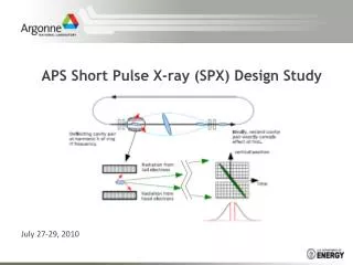
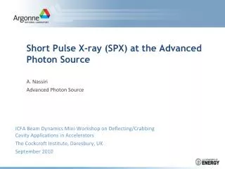
Generating Picosecond X-ray Pulse at APS Through Beam Manipulation Weiming Guo Accelerator Physics Group / ASD Advanced Photon Source
Acknowledgements • Michael Borland • Katherine Harkay • Vadim Sajaev • Chunxi Wang • Bingxin Yang
Outline • Brief review of short pulse generation methods. • Introduce idea of synchrobetatron coupling method. • Linear synchrobetatron coupling and decoherence beam dynamics. • Experimental results. • Conclusions.
Longitudinal Phase Space Manipulation Methods I sd = 0.096% d t sDt = 20 ps • Lower ac • Increase ns: 2nd rf system, lower energy • 3. Voltage modulation
Longitudinal Phase Space Manipulation Methods II dipole d D(s) t 0 Vrf = V0(1+ecosnmw0t)sin hw0t nm~2ns • Lower ac • Voltage modulation
Tilt the Bunch to Get Shorter Pulses y z sy=8mm,0.03ps sz= 5.8mm,20ps sl= sy /q Initial bunch Tilted bunch Photons Slit Shorter Pulse Shorter Pulse
Physics Limits Method Maximum Pulse length Limitation Comp. ratio (ps) Voltage modulation * ~ 2 10 Nonlinearity Increase ns, ns→0.5 ~60 0.3 cavity number Low ac ,fs→1/tE** ~65 0.3 ac,n, x-z coupling Vertical tilt *** ~660 0.03 Physical aper. * Glenn Decker ** Vadim Sajaev *** Michael Borland
Deflecting Cavity and Synchrobetatron coupling y A(z) sin(nxq + y) y Cavity Kick Betatron Osci. A sin(nxq + y(z)) z Magnet Kick Synchrobetatron Coupling y′ y y y y′ y′ y′ ‹y›: Bunch centroid ‹y2›: Bunch height ‹y› (z): Slice centroid ‹y2› (z): Slice beam height
Particle Motion After A Vertical Kick y′ y′ y y After Before the Kick Betatron Oscillation
Tune Difference by Momentum Spread Vertical tune The phase advance due to chromaticity is Longitudinal motion d 2 3 1 Head Tail
Phase Difference by Momentum Spread Vertical tune The phase advance in half synchrotron period Betatron Oscillation Average in one Slice
4 D Phase Space Simulation Initial distribution:Gaussian in both planes Longitudinal phase space: Transverse phase space: Synchrobetatron coupling: Note: simplified simulation, nonlinearity and damping not included.
Simulation Result Bunch shape after ½ synchrotron period Centroid oscillation
Decoherence Concept • If all particles have same oscillation frequency and phase, motion is coherent. • If the oscillation phase is uniformly distributed, the ensemble average is constant, and the particle motion is incoherent. • The progression from coherent motion to incoherent motion is called decoherence. • In accelerators decoherence is usually caused by tune spread, and is accompanied by emittance increase.
Decoherence by Quantum Excitation I Quantum excitation effect Simulation by Elegant
Decoherence by Quantum Excitation II Longitudinal map
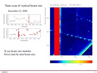
BPM Signal y x Turn Turn V=4kV, I=1.3mA, Cy=2.4, Cx=2.6, ns=0.0078 • X-y coupling • The modulation frequency • Fast decoherence; persistent motion in damping time scale. • The decoherence stops with modulation
BPM Signal Envelop Fit V=4kV, I=1.3mA, Cy=3.5, ns=0.0078, nm=0.0035. • We believe the amplitude tune dependence is small; it has the same feature as quantum excitation decoherence; we hope for one slice under low current, small kick, quantum excitation decoherence dominates.
Experiment Setups for Streak Camera Imaging • Cy was lowered to 4, Cx=6 was unchanged. • We were able to store 1.3 mA current. • The kicker strength applied to the beam was 4kV, or, 0.12 mr, which corresponds to 0.5 mm in the straight sections. The kicker frequency is 2 Hz. • The streak camera was set up to take images turn by turn, in (y,z) plane. Resolution: Y 0.43 ps(0.13mm), Z 2.2 ps. • Images were taken from 0 to 190 turns after the kick, from which we found the best turn to obtain shorter pulses. • The effective slit width was 100 mm.
Streak Camera Measurement Results Pixel size:0.036mm*1.2ps Turn 83-87 Gaussian fit of one slice
Streak Camera Measurement Results The center tilt angle The emittance of the center slice
Shorter Pulse • The current was only 0.2 mA per bunch. • The profile is the overlap of 10 consecutive bunches. • The bunch length was 31 ps. • Streak camera resolution and optical effects are not subtracted. • Turn number • Longitudinal position • Kicker strength • longitudinal tune • Minimum achievable pulse length
Conclusion • Linear synchrobetatron motion • Decoherence caused by quantum excitation • BPM and streak camera data • Effective and convenient • Shortest pulse 3 ps