Download
1 / 64
1.18k likes | 2.03k Views
Chapter5. Vapor and Gas Refrigeration Cycles. Refrigeration Technology. Refrigeration Technology. Chapter5 : Vapor and Gas Refrigeration Cycles. Chapter5. Vapor and Gas Refrigeration Cycles. Mechanical Operated Vapor Compression Refrigeration Cycle

E N D
Chapter5. Vapor and Gas Refrigeration Cycles Refrigeration Technology
Refrigeration Technology Chapter5: Vapor and Gas Refrigeration Cycles Chapter5. Vapor and Gas Refrigeration Cycles • Mechanical Operated Vapor Compression Refrigeration Cycle • Heat Operated Vapor Compression Refrigeration Cycle (1) • Heat Operated Vapor Compression Refrigeration Cycle (2) • Heat Operated Vapor Compression Refrigeration Cycle (3) • Refrigeration Cycle by Gas Compression and Adiabatic Expansion • REFERENCES
Refrigeration Technology Chapter5: Vapor and Gas Refrigeration Cycles Mechanical Operated Vapor Compression Refrigeration Cycle
The mechanical vapor compression refrigeration is the most common refrigeration cycle. Its advantages in comparison with other types of refrigeration are the compact design of the system’s elements; high coefficient of performance (COP); reliability, safety, and flexibility in operation; relative simplicity of its maintenance; and reasonable price. There are some difficulties with security during its operation, but they can be avoided by properly selecting materials and by improving equipment, as well as by choosing appropriate noncorrosive, nonflammable, and nonexplosive refrigerants. Refrigeration Technology Chapter5: Vapor and Gas Refrigeration Cycles 4
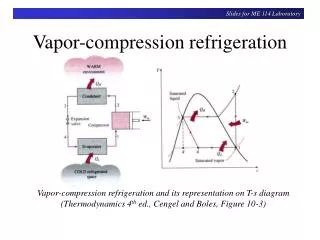
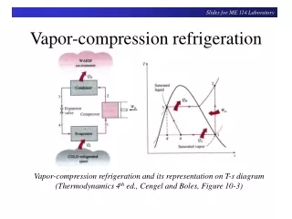
Refrigeration Technology Chapter5: Vapor and Gas Refrigeration Cycles 1. Basic vapor compression refrigeration cycle • The basic vapor compression refrigeration cycle is shown on Fig.5-1. It is composed of the following4 processes: reversible heat addition at pe = const. in evaporation to saturated vapor (from point 4 to point 1); isentropic compression from saturated vapor to the condensing pressure pc (from point1 to point 2); Fig.5-1, Schematic and a log p-h diagram for a basic vapor compression cycle
Refrigeration Technology Chapter5: Vapor and Gas Refrigeration Cycles • reversible heat rejection at pc=const. desuperheating and condensation to saturated liquid, (from point 2 to point 3); • throttling (irreversible process) from high pressure pc to lower pressure pe, (from point 3 to point 4). Fig.5-1, Schematic and a log p-h diagram for a basic vapor compression cycle 6
Refrigeration Technology Chapter5: Vapor and Gas Refrigeration Cycles Here take the Refrigerant R134a as an example. • The refrigerant leaves the evaporator at the temperature of -20℃ and has a condensing temperature of 40℃. • For the case of evaporating temperature te=t1=-20℃ and tc=t3=40℃ the thermal parameters of the states could be found from the diagram or table of the refrigerant R134a as below: • Evaporating pressure • Condensing pressure • The specific enthalpies of these states are:
Refrigeration Technology Chapter5: Vapor and Gas Refrigeration Cycles • The process 1-2 is a reversible, adiabatic (isentropic) compression of the refrigerant. So the specific work input by the compressor is: • The process 2-3 is an internally reversible constant pressure heat rejection process, in which the refrigerant is desuperheated and then condensed to a saturated liquid at point 3. During this process, the refrigerant rejects heat to condensing media. So the specific condensation heat load per unit mass flow rate of refrigerant is: • The process 3-4 is an irreversible throttling process, in which the temperature and pressure of refrigerant both decrease at constant enthalpy:
Refrigeration Technology Chapter5: Vapor and Gas Refrigeration Cycles • The process 4-1 is an internally reversible constant pressure heat admission process, in which the refrigerant is evaporated to a saturated vapor at state point 1. • The heat necessary for evaporation of the refrigerant is supplied by the substance to be cooled. • The rate of heat transferred to the refrigerant in the evaporator is called the refrigeration capacity. • The specific refrigerating effect, i.e. the refrigerating capacity per unit mass flow rate of refrigerant can be obtained as follow: • The coefficient of performance of the cycle can be calculated as:
Refrigeration Technology Chapter5: Vapor and Gas Refrigeration Cycles Heat Operated Vapor Compression Refrigeration Cycle
Conventional cooling systems utilize mechanical compressors that are driven by electricity. However, the wide-spread application of cooling, and air-conditioning systems in summer could overload electricity supplies and use of the electricity generated from fossil fuels has a serious impact on the environment. These problems could be eased by utilization of alternative energy sources for refrigeration and air-conditioning systems. Thermal energy is one that looks promising. There is abundant thermal energy appeared in different forms in the world, such as solar thermal, geothermal, various wasted heats and biomass energy etc. These energies can be used to drive refrigeration and air-conditioning systems. Refrigeration Technology Chapter5: Vapor and Gas Refrigeration Cycles 11
There are three kinds of vapor compression refrigeration cycles that can be driven by thermal energy. They are: the absorption refrigeration cycle the adsorption refrigeration cycle the vapor jet refrigeration cycle Refrigeration Technology Chapter5: Vapor and Gas Refrigeration Cycles 12
Heat Operated Vapor Compression Refrigeration Cycle (1) Refrigeration Technology Chapter5: Vapor and Gas Refrigeration Cycles ------Vapor Absorption Refrigeration 13
Refrigeration Technology Chapter5: Vapor and Gas Refrigeration Cycles • Principles of absorption refrigeration • Both the mechanical vapor compression refrigeration cycle and the absorption refrigeration cycle accomplish the removal of heat through the evaporation of a refrigerant at a low pressure and the rejection of heat through the condensation of the refrigerant at a higher pressure. • The method of creating the pressure difference and circulating the refrigerant is the primary difference between the two cycles. • The mechanical vapor compression cycle employs a mechanical compressor to create the pressure difference necessary to circulate the refrigerant. • In the absorption system, another liquid, which is called absorbent, is used to circulate the refrigerant.
Refrigeration Technology Chapter5: Vapor and Gas Refrigeration Cycles • The main components of a basic absorption system are shown diagrammatically in Fig.5-2 . • Comparing the left part of Fig.5-1, it can be seen that the condenser, expansion valve and evaporator in these two cycles are the same, the mechanical compressor, however, is replaced by a thermal compressor which consists of absorber, solution pump, generator (or boiler) and liquid valve. Fig.5-2, essential components of the vapor absorption cycle
Refrigeration Technology Chapter5: Vapor and Gas Refrigeration Cycles • This group of components ‘sucks’ vapor from the evaporator, and delivers high pressure vapor to the condenser, just as the mechanical compressor does but the vapor is actually absorbed by a liquid absorbent . • Aqua ammonia and aqua lithium bromide solutions are commonly used in vapor absorption refrigeration systems Fig.5-2, essential components of the vapor absorption cycle 16
Refrigeration Technology Chapter5: Vapor and Gas Refrigeration Cycles • In an ammonia-water absorption system, ammonia is used as the refrigerant and water as the absorbent. • In lithium bromide-water absorption refrigeration systems, water is the refrigerant and lithium bromide is the absorbent. • This explains that the lithium bromide absorption system is strictly limited to evaporation temperatures above 0ºC; and the ammonia absorption system is mainly used for low temperatures below 0ºC.
2. Composition of mixtures Calculation of absorption refrigerators requires some knowledge of the thermodynamics of solutions and of how their properties depend on the composition. Composition of a mixture is expressed as the mass fraction ξ of one of the components. For example, in H2O–LiBr solution it contains mass mLof LiBr and mW of H2O, the mass fraction of LiBr is defined as: Refrigeration Technology Chapter5: Vapor and Gas Refrigeration Cycles 18
Refrigeration Technology Chapter5: Vapor and Gas Refrigeration Cycles • And the mass fraction of H2O is: • Mixing two masses m1 and m2of solutions having the mass fraction ξ1 and ξ2, respectively, produces a solution having the intermediate mass fraction ξ3. • From the constancy of the mass of LiBr before and after:
Refrigeration Technology Chapter5: Vapor and Gas Refrigeration Cycles 2. Vapor pressure of LiBr-water solution • The vapor pressure of aqua lithium bromide solution is determined by its temperature and mass fraction. Their relationship is shown in Fig.5-3. • The abscissa is temperature in linear scale; the ordinate on the left-hand is vapor pressure in logarithmic scale; the ordinate on the right-hand is temperature in linear scale, shows the saturation temperature of pure water which has the same vapor pressure as a BrLi solution at the temperature given by the abscissa. Fig.5-3, the vapor pressure of solutions of LiBr in water [6]
Refrigeration Technology Chapter5: Vapor and Gas Refrigeration Cycles • The line of pure water is also shown in the figure, which is corresponding to a solution of ξ=0 , all the points on the line of pure water have the same values of temperature both on the abscissa and on the ordinate on the right-hand. Fig.5-3, the vapor pressure of solutions of LiBr in water [6] 21
Refrigeration Technology Chapter5: Vapor and Gas Refrigeration Cycles 3. Basic Lithium bromide-water absorption refrigeration system • The diagram shown in Fig.5-4 is a basic lithiumbromide vapor absorption refrigeration system. • A basic H2O–LiBr absorption refrigeration system consists of 8 main components. • Apart from the evaporator, the condenser and the expansion valve which are found in a mechanical powered vapor compression refrigerator, other five components, namely, a pump, and absorber, a generator, a heat exchanger and a valve fulfill the function of “thermal compressor”: Fig.5-4, a scheme of a basic absorption refrigeration system
Refrigeration Technology Chapter5: Vapor and Gas Refrigeration Cycles • In the evaporator, the heat (Qe) from low temperature source (To) is transferred to the refrigerant which changes its state from liquid to vapor at low pressure from state 3 to state 4. • The vapor is then absorbed by the absorbent LiBr in the absorber at low pressure and temperature. • During the absorption, the vapor changes into liquid state 5. • The absorption is an exothermic process. • The heat (Qa) released during the absorption process is rejected to the surroundings. • The weak solution is delivered by the pump to the generator (G) at high pressure at the state 7. • The solution in the generator is heated to boil off the refrigerant (water) with heat (Qb) from the high temperature source so that the solution is concentrated.
Solution in the generator becomes strong and leaves the generator at state 8. The high pressure and temperature refrigerant vapor at state 1 leaves the generator and flows to the condenser where the refrigerant is cooling down and condensed. The condensing heat (QC) is rejected to the surroundings. The liquid refrigerant then expands through the expansion valve (RV1) from state 2 to state 3. This completes the refrigerant cycle. The strong solution leaving the generator flows back to the absorber after passing through the valve (RV2) and changing its state from state 9 to 10 to complete the solution circulation. It worth noting that the compression done by the pump in the absorption system only consumes a small amount of mechanical work (Wp). Refrigeration Technology Chapter5: Vapor and Gas Refrigeration Cycles 24
Refrigeration Technology Chapter5: Vapor and Gas Refrigeration Cycles 4. Analysis for a basic absorption refrigeration system (1) Circulation factor • In an absorption refrigeration system, the solution changes its mass fractions in the absorption process. • For the lithium bromide absorption system, the mass fractions before and after absorption are denoted by ξs and ξw , respectively. • An important quantity in the calculation of an absorption system is the mass flow rate of the strong solution which is needed to absorb unit mass flow rate of vapor from the evaporator. • This quantity is called the circulation factor λ. • Since the mass of lithium bromide in the solution does not change in the absorption process, therefore, the following equation exists:
Refrigeration Technology Chapter5: Vapor and Gas Refrigeration Cycles (2) Enthalpy of liquid and vapor • Fig.5-6 shows the enthalpy of solutions of lithium bromide in water, which is based on Lower’s values. [9] • The figure is based on the enthalpies of liquid water and solid anhydrous lithium bromide each being zero at 0℃. • From this chart, the enthalpies of the LiBr-water solution may be obtained, if the temperature and the mass fraction of solutions are given. Fig.5-6, specific enthalpy of solutions of LiBr in water
Refrigeration Technology Chapter5: Vapor and Gas Refrigeration Cycles 5. Multiple-Effect and direct- or indirect-fired Absorption Chillers • Absorption chillers can be direct- or indirect-fired and single- or multiple-effect. • Fig.5-7 shows a double-effect absorption cycle. • Double-effect absorption machines uses two generators paired with a single condenser, absorber, and evaporator. • The higher-temperature generator (1) is called the first stage-generator. • The refrigerant vapor produced in the generator (1) is then used to desorb additional refrigerant (water) from a lower-temperature, the second-stage generator (2). Fig.5-7, a double-effect absorption cycle [10]
Refrigeration Technology Chapter5: Vapor and Gas Refrigeration Cycles • So heat energy from the first stage is recovered and is utilized in the second stage. Consequently, a double-effect absorption cycle is more efficient than a single-effect one. • For example of a LiBr absorption system used for air conditioning, the heat ratio of absorption chillers ranges from 0.60 to 0.70 for indirect-fired single-effect systems, to about 1.20 for indirect-fired double-effect units. Fig.5-7, a double-effect absorption cycle [10] 28
Refrigeration Technology Chapter5: Vapor and Gas Refrigeration Cycles • Fig.5-8 shows a triple-effect absorption chiller-heater which has three generators: high-temperature, intermediate-temperature and low-temperature. • The structure is similar to that of conventional double-effect systems except for the additional generator that is included. • The heat ratio , or cooling coefficient of performance (COP), higher than that of double-effect systems can be obtained by heating the generators with a high-temperature heat source such as city gas and then utilizing cascading heat in the absorption cycle process. • The high-temperature generator in a triple-effect system is exposed to a higher temperature and higher pressure than in a double-effect system. Fig.5-8, a Triple-effect absorption chiller-heater (H.T. -High-temperature, I.T. -Intermediate-temperature, L.T. -Low-temperature)
Refrigeration Technology Chapter5: Vapor and Gas Refrigeration Cycles • Some disadvantages associated with lithium bromide absorption refrigeration systems are: the risk of crystallization of solution at high concentrations; the corrosion in the system can occur. • Lithium bromide, a highly corrosive brine, readily attacks ferrous metals such as steel. • The corrosion process generates hydrogen gas that reduces the internal vacuum inside the evaporator, which results in the unit operating poorly. • In addition, the debris resulting from the corrosion fouls narrow openings in spray headers, heat exchangers, etc.
Refrigeration Technology Chapter5: Vapor and Gas Refrigeration Cycles 6. The Ammonia-Water Absorption System • Principles of the ammonia-water absorption system • In ammonia-water absorption system, water is a absorbent, ammonia is a refrigerant. • Operation of the refrigeration cycle is conventional with high pressure refrigerant entering the receiver from the condenser before passing to an expansion valve and an evaporator where heat is absorbed from the process. • The remaining items in the system replace the conventional compressor to achieve “thermal” compression.
(2) Analysis of the ammonia-water absorption cycle The composition of ammonia in water solutions is expressed by the mass fraction exactly as for solutions of lithium bromide in water. But the symbol ξstands for the mass fraction of ammonia, i.e. the refrigerant and the adjectives strong and weak will mean strong and weak in ammonia. Refrigeration Technology Chapter5: Vapor and Gas Refrigeration Cycles 32
Refrigeration Technology Chapter5: Vapor and Gas Refrigeration Cycles • Referring to Fig.5-9, the cycle beginning at point 5” where nearly pure vapor leaves the rectifier at the condensing pressure pc. • The vapor is condensed in the condenser to saturated liquid state at point 6. • This liquid then passes through the expansion valve to point 7 and enters into the evaporator where it becomes saturated or slightly superheated vapor at point 8 at the pressure pe. • So far the discussed operations are concerned with pure ammonia and are exactly the same as those in a mechanical vapor compression refrigerator. • The vapor from the evaporator is absorbed by the weak solution with mass fraction in the absorber at the state 3. Fig.5-9, a typical ammonia absorption system
Refrigeration Technology Chapter5: Vapor and Gas Refrigeration Cycles • This weak solution is originated in the boiler as liquid, 2, at its bubble point and is subsequently cooled in the heat exchanger to point 2a. • Then it passes through the valve to pressure paat 3. • The solution 4 then passes through the pump to point 4a. • In compression a liquid there is only a very small change in temperature. • In the heat exchanger the solution temperature rises to point 1a at the same mass fraction. • The state 1a depends on the amount of heat transferred by the heat exchanger. Fig.5-9, a typical ammonia absorption system 34
Refrigeration Technology Chapter5: Vapor and Gas Refrigeration Cycles • The specific enthalpy of vapor in equilibrium with aqua ammonia solution is shown in Fig.5-10. • In Fig.5-10, the left-hand family of curves are plotted against the mass fraction of ammonia in the liquid, ξ′; the right-hand family of curves are plotted against the mass fraction of ammonia in the equilibrium vapor, ξ〞. Fig.5-10, specific enthalpy of vapor in equilibrium with a solution of ammonia in water [1]
So the processes of ammonia-water absorption cycle described above as shown in Fig 5-9 can be expressed in Fig.5-11. Refrigeration Technology Chapter5: Vapor and Gas Refrigeration Cycles Fig.5-11, the h-ξdiagram for the processes in Fig.5-9 • From the Fig.5-10 and Fig.5-11, the enthalpies of all the state points can be found. • Then the thermodynamic calculation of the ammonia-water absorption system will be easily carried out by referring to the calculation method for the lithium bromide-water absorption system. 36
Refrigeration Technology Chapter5: Vapor and Gas Refrigeration Cycles Heat Operated vapor Compression Refrigeration Cycle (2) ------Vapor Adsorption Refrigeration
1. Adsorption and desorption (1) Adsorption Adsorption is a process that occurs when a gas or liquid solute accumulates on the surface of a solid or a liquid (adsorbent), forming a film of molecules or atoms (the adsorbate). The term sorption encompasses both processes, while desorption is the reverse process of adsorption. Refrigeration Technology Chapter5: Vapor and Gas Refrigeration Cycles 38
Refrigeration Technology Chapter5: Vapor and Gas Refrigeration Cycles (2) Desorption • Desorption is a phenomenon whereby a substance is released from or through a surface. • The process is the opposite of sorption (that is, adsorption and absorption). • As the temperature rises, so does the likelihood of desorption occurring.
Refrigeration Technology Chapter5: Vapor and Gas Refrigeration Cycles 2. The working pairs in adsorption refrigeration Tab.5-2, the main working substances in adsorption refrigeration • Most industrial adsorbents fall into one of three classes: • Oxygen-containing compounds – Are typically hydrophilic and polar, including materials such as silica gel and zeolites. • Carbon-based compounds – Are typically hydrophobic and non-polar, including materials such as activated carbon. • Polymer-based compounds - Are polar or non-polar functional groups in a porous polymer matrix.
Refrigeration Technology Chapter5: Vapor and Gas Refrigeration Cycles 3. Principles of adsorption refrigeration • Like the the mechanical vapor compression refrigeration cycle and the absorption refrigeration cycle, the adsorption refrigeration cycle can accomplish the removal of heat through the evaporation of a refrigerant at a low pressure and the rejection of heat through the condensation of the refrigerant at a higher pressure. • The pressure difference in the adsorption refrigeration system is created by adsorption and desorption of refrigerant vapor by adsorbent at low temperature and at high temperature respectively, as shown in Fig.5-13. Fig.5-13, essential components of the vapor absorption cycle
Refrigeration Technology Chapter5: Vapor and Gas Refrigeration Cycles • An adsorption cycle for refrigeration (or heat pumping) does not use any mechanical energy, but only heat energy. • Moreover, this type of cycle basically is a four temperature discontinuous cycle. The cycle consists of four periods as shown in Fig.5-14. Fig.5-14 Heating and desorption + condensation
(1) Heating and pressurization During this period, the adsorber receives heat while being closed. The adsorbent (refrigerant)temperature increases, which induces a pressure increase, from the evaporation pressure up to the condensation pressure. (2) Heating and desorption + condensation During this period, the adsorber continues receiving heat while being connected to the condenser, which now superimposes its pressure. The adsorbent temperature continues increasing, which induces desorption of vapor. This desorbed vapor is liquefied in the condenser. (3) Cooling and depressurization During this period, the adsorber releases heat while being closed. The adsorbent temperature decreases, which induces the pressure decrease from the condensation pressure down to the evaporation pressure. Refrigeration Technology Chapter5: Vapor and Gas Refrigeration Cycles 43
Refrigeration Technology Chapter5: Vapor and Gas Refrigeration Cycles (4) Cooling and adsorption + evaporation • During this period, the adsorber continues releasing heat while being connected to the evaporator, which now superimposes its pressure. • The adsorbent temperature continues decreasing, which induces adsorption of vapor. • This adsorbed vapor is vaporized in the evaporator. • The evaporation heat is supplied by the heat source at low temperature. • For a single absorber system, the cycle is intermittent because cold production is not continuous: cold production proceeds only during part of the cycle. • When there are two adsorbers in the unit, they can be operated out of phase and the cold production is quasi-continuous.
Refrigeration Technology Chapter5: Vapor and Gas Refrigeration Cycles • For a single absorber system, the cycle is intermittent because cold production is not continuous: cold production proceeds only during part of the cycle. • When there are two adsorbers in the unit, they can be operated out of phase and the cold production is quasi-continuous.
In comparison with mechanical vapor compression systems, adsorption systems have the benefits of energy saving if powered by waste heat or solar energy, simpler control, no vibration and lower operation costs. In comparison with liquid absorption systems, adsorption ones present the advantage of being able to be powered by a large range of heat source temperatures, starting at 50℃ and going up to 500℃. Moreover, the latter kind of system does not need a liquid pump or rectifier for the refrigerant, does not present corrosion problems due to the working pairs normally used, and it is also less sensitive to shocks and to the installation position. Refrigeration Technology Chapter5: Vapor and Gas Refrigeration Cycles 46
Heat Operated vapor Compression Refrigeration Cycle (3) ------Vapor Jet Refrigeration Refrigeration Technology Chapter5: Vapor and Gas Refrigeration Cycles 47
Refrigeration Technology Chapter5: Vapor and Gas Refrigeration Cycles • Principles of vapor jet refrigeration systems • Vapor jet refrigeration is other type of vapor compression refrigeration cycle driven by heat source of high temperature. • As the same as the mechanical vapor compression refrigeration cycle, the vapor jet refrigeration cycle can accomplish the removal of heat through the evaporation of a refrigerant at a low pressure and the rejection of heat through the condensation of the refrigerant at a higher pressure. • The pressure difference in the system is created by a high pressure vapor or steam ejector, as shown in Fig.5-15.
Refrigeration Technology Chapter5: Vapor and Gas Refrigeration Cycles • The refrigerant in the system shown in Fig.5-15 is water. • A supply of high-pressure vapor, usually steam, passes through a nozzle in which it acquires a high velocity and some vacuum whilst expanding down to evaporator pressure. Fig.5-15, refrigeration system using a steam ejector or thermo-compressor
Refrigeration Technology Chapter5: Vapor and Gas Refrigeration Cycles • This steam, known as the motive steam, shares its momentum with vapor from the evaporator so that the resulting mixture has sufficient velocity to move against the pressure gradient up to the condenser pressure in a diffuser, in which the mixture is decelerated and compressed. • Both the motive vapor and the vapor drawn from the evaporator are condensed, and the condensate is then divided into two flows, one to pass an expansion valve and feed the evaporator and the other to supply the boiler of motive steam through a feed pump. Fig.5-15, refrigeration system using a steam ejector or thermo-compressor 50