Download
1 / 61
620 likes | 774 Views
This course, taught by Lecturer Mohd Fisol Bin Osman, covers the fundamentals of multimedia technology, including data, voice, and video communication principles. It explores various networking media, devices, and software, emphasizing their integration in communication services. Key topics include telecommunications structures, wireless technologies, and the functionalities of transmitters and receivers. Students will engage in lectures and hands-on laboratory sessions to develop practical and theoretical knowledge, ultimately preparing them to analyze and propose effective communication designs.

E N D
PGT110 – MULTIMEDIA TECHNOLOGY Lecturer/PLV : MohdFisol Bin Osman Email : mohd.fisol@unimap.edu.my Mobile : 019 - 3528363
Date and Time • Lecture Monday : 5 PM to 7 PM (2 Hours) • Laboratory/Tutorial Session (3 Hours) Divided into two groups : Group 1 : Friday 4 PM to 7 PM Group 2 : 12 Noon to 3 PM Attendance will be recorded !
Course Outcomes (Cos) • CO1 : Ability to identify the fundamentals and concepts of data, voice and video communications and the criteria for choosing a communications medium. • CO2 : Ability to explain how networking media, devices and software work together to provide data, voice and video networking services and describes the benefits of various types of media.
COs Continue.. • CO3 : Ability to list and analyze wireless telecommunications technologies and its structure • CO4 : Ability to evaluate and propose basic telecommunication design structure based on conditions given
Chapter 1 – Overview of Multimedia Systems (Concepts and Definations) • Dedicated, switched, and virtual circuits • Two wires vs four wires circuits • Analog vs Digital • Amplifiers, Repeaters • Modem and Codecs • Multiplexers and Switchers • Signaling and Controls
Preface “What is the transmitter? It is an electrical ear which receives the shock of the dancing molecules, just as does the membrane of the human ear. . . . What is the receiver? It is an electric mouth which can utter human sounds. “ John Mills, The Magic of Communication: A Tell - You - How Story, Information Department, American Telephone and Telegraph Company
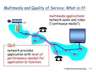
Telecommunications General definition: Telecommunications is the transfer of information ( communications ) from a transmitteror sender to a receiver across a distance ( tele) through a transmission medium • Electromagnetic energy is employed to represent the data, usually through a physical/transmission medium, such as: • copper wire or glass fibre What else?. wired/ wireless ? NEXT : INFORMATION
Information • Information can be in many form - electromagnetic energy • Electric impulse • Radiated energy • The information can retain its original, or native, form during transmission. • Alternatively, the transmission process can alter the data in some way in order to effect compatibility between the transmit and receive devices and with various intermediate network elements. List several types/forms of information :
Information (Cont.) • Audio/Voice • Human voice, CDs, tape, records, radio etc • Video • movies, graphics and animation • Data • Emails, messages etc • Image • Combinations/Multimedia
Intermediate devices • toestablishand maintain the connection and to support the information transfer. Examples: • modems or codecs, • controllers, • multiplexers • bridges, switches, routers, • Gateways • ETCs..
Transmitter • The transmitter is a collection of electronic components and circuits that converts the electrical signal into a signal suitable for transmission over a given medium. • Transmitters are made up of oscillators, amplifiers, tuned circuits and filters, modulators, frequency mixers, frequency synthesizers, and other circuits.
Communication Channels/ Transmission Mediums • The communication channel is the medium by which the electronic signal is sent from one place to another. • Types of media include • Electrical conductors • Optical media • Free space
Receivers • A receiveris a collection of electronic components and circuits that accepts the transmitted message from the channel and converts it back into a form understandable by humans. • Receivers contain amplifiers, oscillators, mixers, tuned circuits and filters, and a demodulator or detector that recovers the original intelligence signal from the modulated carrier
Transceivers • A transceiveris an electronic unit that incorporates circuits that both send and receive signals. • Examples are: • Telephones • Fax machines • Handheld CB radios • Cell phones • Computer modems
Noise • random, undesirable electronic energy that enters the communication system via the communicating medium and interferes with the transmitted message.
Souce Other words for transmitter • Device that originates the information transfer. • Transmitters include voice telephones, data terminals, host computer systems, and video cameras.
Sink Other word for receiver/ destination • target device, or destination device, that receives the information transfer. • Receivers can include telephones, data terminals, host computers, and video monitors. • Most devices are capable of both transmitter and receiver functions (source/sink)
Circuit • a communications path, over an established medium, between two or more points, from end to end, between transmitter and receiver • logical connection over a physical line • Might include path, link, line , and channel , although such usage can be specifi c to the underlying technology • Circuits also may be for purposes of either access (from the customer premises to the edge of the carrier network) or transport (circuits are employed in the core , or backbone , of the network for purposes of long - haul transmission) • simplex (one - way), half - duplex (two - way, but only one way at a time), or full - duplex (simultaneous two - way)
Link • two - point segment of an end - to - end circuit (e.g., from terminal to switch or from switch to switch) • Either single link or multiple links • Example: between a host computer and a peripheral, such as a printer
Line • Has several definitions • In a Private Branch eXchange (PBX) environment, a station line refers to the connection between the PBX switch and the station user ’ s terminal equipment, such as telephone, fax machine etc. • In rate and tariff terminology, line refers to a local loop connection from the telephone company Central Office (CO) switch to the user premises in support of Customer Premises Equipment (CPE) other than a switch.
Trunk • a communications circuit, available to share among multiple users, on a pooled basis and with contention for trunk access managed by an intelligent switching device • trunks interconnect switches • Trunks are directional in nature, with the options being one - way outgoing (originating), one – way incoming (terminating), or two - way (combination).
Dedicated, Switched and Virtual Circuits Dedicated Circuits between Seattle terminal and New York Mainframe
DedicatedCircuits • physical circuits dedicated to directly connecting devices (e.g., PBXs and host computers) across a network Advantages: • serve a single - user organization only, rather than serving multiple users • Ability to condition dedicated circuits to deliver specific levels of performance by adding amplification or other signal processing enhancements to the line to optimize its transmission characteristics, whereas you generally cannot do so with switched circuits(not from end to end).
Dedicated circuits Disadvantages: • In terms of network efficiency because that circuit is taken out of shared public use and, therefore, is unavailable for use in support of the traffic of other users • rather expensive- with their costs being sensitive to distance and capacity • susceptible to disruption, backup circuits often are required to ensure effective communications in the event of either a catastrophic failure or serious performance degradation. • Could be difficult and lengthy design and configuration process. – for huge connections
Switched Circuits Example of circuit switched connections
Switched Circuits • More flexible
Virtual Circuits • logical, rather than physical, circuits. • are established through the network based on options and instructions defined in software routing tables • Divided into two: - Permanent Virtual Circuits (PVCs) - Switched Virtual Circuits (SVCs) • Will learn more in chapter 10 !..Broadband Network Services
Two wires vs Four wires Circuit Comparison of Two wires and Four wires Circuits
Two wires circuit • carry information signals in both directions over the same physical link or path • The use of a single twisted pair, copperwireconnection • two wires are required to complete the electrical circuit, with the current in one wire opposite to the current in the other, and both wires carry the information signal • generally cover a short distance • gener-ally they are analog in nature; therefore, error performance (quality) is relatively poor
Four wire circuit • carry information signals in both directions over separate physical links or paths and in support of simultaneous, two - way transmission. • Traditional – used copper wires, nowadays over a variety of transmission media, including twisted pair, coaxial cable, or fiber optic cable • can be established without the use of any wires at all, as in the case with a circuit established over microwave, satellite, or infrared transmission systems.
Four wire circuit Advantages : • Can accommodate multiple, simultaneous communications in a full - duplex mode, all multichannel circuits are four wire. Multichannel capability • greater bandwidth, or capacity • digital, rather than analog – improve error performance
Bandwidth • measure of the capacity of a circuit or channel • the total frequency on the available carrierfor the transmission of data. • While the information signal (bandwidth usable for data transmission) does not occupy the total capacity of a circuit, it generally and ideally occupies most of it. • The balance of the capacity of the circuit may be used for various signaling and control (overhead ) purposes
Carrier • continuous signal on a circuit that is at a certain frequency or within a certain frequency range • support of the information bearing signal (i.e., it carries the information signal), which the transmitter impresses on the carrier by varying the signal in some fashion and which the receiver must detect and interpret • support signaling and • control information used to coordinate and manage various aspects of network operations
Types of Communications Two-way Half duplex: Alternate TX/RX Duplex: Full duplex: Simultaneous TX/RX Simplex: One-way TX RX Channel TX RX Channel(s) TX RX
Types of Communication Signals Analog - smooth and continuous voltage variation. Digital - binary or two voltage levels. Time
Communications Signal Variations • Baseband - The original information signal such as audio, video, or computer data. Can be analog or digital. • Broadband - The baseband signal modulates or modifies a carrier signal, which is usually a sine wave at a frequency much higher than the baseband signal.
Basic analog communications system Baseband signal (electrical signal) EM waves (modulated signal) Transmitter Input transducer Transmission Channel Modulator EM waves (modulated signal) Carrier Baseband signal (electrical signal) Receiver Output transducer Demodulator
MODULATION • An electronic technique in which a baseband information signal modifies a carrier signal (usually a sine wave) for the purpose of frequency translation and carrying the information signal via radio. • The common types of modulation are amplitude, frequency and phase.
Why modulation is needed? • To generate a modulated signal suited and compatible to the characteristics of the transmission channel. • For ease radiation and reduction of antenna size • Reduction of noise and interference • Channel assignment • Increase transmission speed
High-frequency carrier, normally much higher than the baseband frequency AMPLITUDE MODULATION The modulating (baseband) signal is a sinusoid in this example.
FREQUENCY MODULATION The baseband signal controls the carrier’s frequency and the carrier’s amplitude remains constant.
Increasing fc Decreasing fc Increasing fc Resting fc Resting fc FM Modulating signal Carrier
MULTIPLEXING • Multiplexing (MUX or MPX) - the process of simultaneously transmitting two or more baseband information signals over a single communications channel. • Demultiplexing (DEMUX or DMPX) - the process of recovering the individual baseband signals from the multiplexed signal.
Single communications channel (radio or cable) Recovered baseband information signals Original baseband information signals MULTIPLEXING AND DEMULTIPLEXING MUX DEMUX
FREQUENCYANDWAVELENGTH • Cycle - One complete occurrence of a repeating wave (periodic signal) such as one positive and one negative alternation of a sine wave. • Frequency - the number of cycles of a signal that occur in one second. • Period- the time distance between two similar points on a periodic wave. • Wavelength - the distance traveled by an electromagnetic (radio) wave during one period.