Download
1 / 30
340 likes | 642 Views
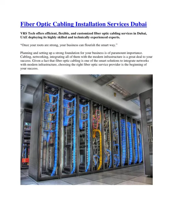
Guidelines for Fiber Optic Design and Installation. Ch 9 Fiber Optics Technician’s Manual, 3 rd . Ed Jim Hayes. General Guidelines. List Specifications Know just what you want Find Out how Performance Numbers were Measured

E N D
Guidelines for Fiber Optic Design and Installation Ch 9 Fiber Optics Technician’s Manual, 3rd. Ed Jim Hayes
General Guidelines • List Specifications • Know just what you want • Find Out how Performance Numbers were Measured • If a vendor says you can terminate each fiber in 3 minutes, make sure that’s really true
General Guidelines • 4 Vendors for Each Component • See table • Talk With Vendors Who Know More Than You Do • Avoid “the blind leading the blind” • Expect and Resolve Contradictions • Use Vendors With 5 Years in Business
General Guidelines • Use “High Serial Numbers” • Tried and True • Design Decisions Impact Cost • Wavelength, connectors, cable • Buy Only Performance you Need • Ask Vendors About Competitors
Cable Guidelines • Check for Bargain Products Close to Your Needs • Leftovers, or with unimportant defects • Look for Best Price Possible • Often there are great deals • Be cautious about paying for premium fiber • Calculate the bandwidth limits to make sure you really need it
Other Considerations • Most manufacturers of cable provide about the same level of reliability
Connector Guidelines • No connector type is “the best” • Some are cheaper • Some are easier to install • Some require special tools • etc. • Ceramic Ferrules • They are all manufactured by the same few companies • Price and performance should not vary much
Connector Guidelines • Ease of Installation May Lead to Poor Performance • Unicam-type connectors (no adhesive) use clamps to hold the fiber • They are subject to “pistoning” • Fiber moving in and out under thermal stress
Pistoning causes cracking on optical fiber endface Image from nasa.gov (link Ch 9a) Pistoning Damage Pre thermal testing Post thermal testing
Connector Guidelines • There is no Substitute for Experience • Connectorization is a skill that requires constant practice
Cable Plant Link Loss Budget Analysis Ch 10 Fiber Optics Technician’s Manual, 3rd. Ed Jim Hayes
Power Distance Link Loss Budget Splice Transmit-ter Receiver Connector Connector Link LossMargin Receiver Sensitivity
Losses • Light is lost by • Distance along fiber (attenuation) • Connector pairs • Splices • Splitters (if any)
Loss and Bandwidth • Loss is an important measure of a network’s quality • But for high data rates the bandwidth of the fiber can also be important
Attenuation-Limited Networks • Some networks are attenuation-limited • The max. length is determined by power loss • Adding another connector pair means the network must be shortened
Low Data Rate • This is an Attenuation-Limited Network • Standard 62.5/125 micron multimode • 0.75 dB loss per connector pair • 3.5 dB loss per km • 1 Gb/s
Dispersion-Limited Networks • Some networks are dispersion-limited • The max. length is determined by spreading of the light pulses • Adding another connector pair does not affect max. length, until the loss becomes very severe
High Data Rate • This is a Dispersion-Limited Network • Standard 62.5/125 micron multimode • 0.75 dB loss per connector pair • 3.5 dB loss per km • 10 Gb/s
Link Margin • Just take the difference between transmitter power and receiver sensitivity • Example: • T=-20 dBm R = -30 dBm • Link Margin = 10 dB • The loss of the total cable system must not exceed the Link Margin
Example: Media Converters • Top line: device with a link margin of 7 dB • 4th line: device with a link margin of 24 dB • Last line: link margin of 7.5 dB • From link Ch 3h (arcelect.com)
Attenuation • Typical Attenuation for Multimode fiber: • 3 dB/km @ 850 nm • 1 dB/km @ 1300 nm • Typical Attenuation for Singlemode fiber: • 0.4 dB/km @ 1310 nm • 0.25 dB/km @ 1550 nm
Connector Loss • Typically 0.2 – 0.5 dB per mated pair of connectors • Industry standard max. 0.75 dB • A single connector has “no loss” – the light comes out of it • The measurable unit is a connector pair
Splice Loss • Mechanical splices – 0.3 dB max., 0.2 typical • Fusion splices – 0.05 dB max.
Stress Loss • Poor installation practices can stress the fiber, causing loss • Pulling with too much tension • Bending past the allowable bend radius • Tight cable ties
Calculated Loss Budget • Using standard values, calculate the expected loss of the link • Actual measured loss should be less • If it is higher, something is wrong
Splice Transmit-ter Receiver Connector Connector Cable Plant Passive Component Loss Calculation • MM @1300 nm; typical values • 2 km length x 1dB/km = 2.0 dB • 4 connector pairs x 0.5 dB = 2.0 dB • 1 splice (mechanical) x 0.2 dB = 0.2 dB • Total = 4.2 dB
Equipment Link Loss Budget Calc. • Last line: dynamic range of 7.5 dB • Recommended excess margin: 3 dB • Maximum cable plant loss: 4.5 dB • So our cable plant with 4.2 dB has a link loss margin of 0.3 dB
To Prepare for the Next Quiz • Study the questions on p. 137-138 • I plan to give you a problem like that
Splice Transmit-ter Receiver Connector Connector Cable Plant Passive Component Loss Calculation • MM @850 nm; typical values • 2 km length x 3dB/km = 6.0 dB • 4 connector pairs x 0.5 dB = 2.0 dB • 1 splice (mechanical) x 0.2 dB = 0.2 dB • Total = 8.2 dB