Download
1 / 25

E N D
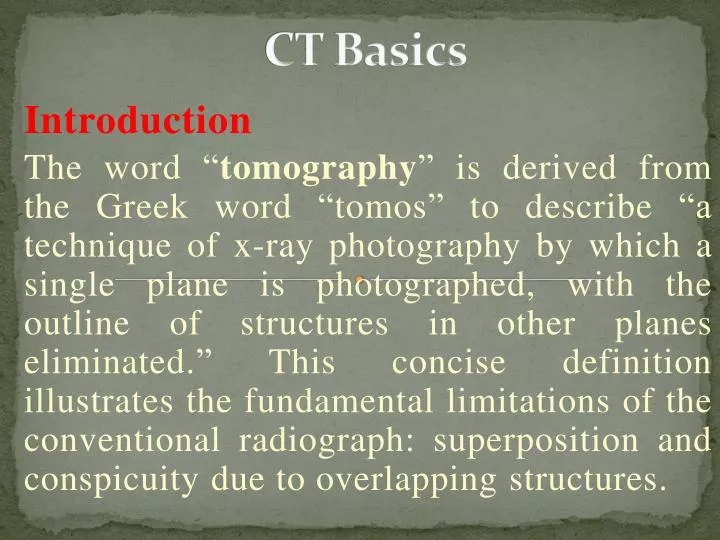
CT Basics Introduction The word “tomography” is derived from the Greek word “tomos” to describe “a technique of x-ray photography by which a single plane is photographed, with the outline of structures in other planes eliminated.” This concise definition illustrates the fundamental limitations of the conventional radiograph: superposition and conspicuity due to overlapping structures.
In conventional radiography, the three-dimensional (3D) volume of a human body is compressed along the direction of the x ray to a two-dimensional (2D) image, as shown in Fig. 1.1(a). • All underlying bony structures and tissues are superimposed, which results in significantly reduced visibility of the object of interest. Figure 1.1(b) shows an example of a chest x-ray study.
Figure 1.1 Illustration of conventional x ray. (a) Acquisition setup and (b) example of a chest study.
The superposition of the ribs, lungs, and heart is quite evident. Consequently, despite the image’s superb spatial resolution (the ability to resolve closely placed high contrast objects), it suffers from poor low-contrast resolution (the ability to differentiate a low-contrast object from its background). A recognition of this limitation led to the development of conventional tomography.
1.1 Conventional X-ray Tomography • Conventional tomography is also known as planigraphy, stratigraphy, laminagraphy, body section radiography, zonography, or noncomputed tomography. • One of the pioneers of conventional tomography was A. E. M. Bocage. As early as 1921, Bocage described an apparatus to blur out structures above and below a plane of interest.
The major components of Bocage’s invention consisted of an x-ray tube, an x-ray film, and a mechanical connection to ensure synchronous movement of the tube and the film. The principle of conventional tomography is illustrated in Fig. 1.2. For convenience, consider two isolated points, A and B, located inside a patient. Point A is positioned on the focal plane and point B is off the focal plane. The shadows cast on the x-ray film by points A and B are labeled A1 and B1, respectively, as shown in Fig. 1.2(a).
The image produced on the film at this instant is not at all different from a conventional radiograph. Next, we move both the x-ray source and the x-ray film synchronously in opposite directions (for example, the x-ray source moves to the left and the film moves to the right, as shown in the figure) to reach a second location. We want to make sure that the shadow A2 produced by the stationary point A overlaps with the shadow A1 produced by point A in the first position.
This can be easily accomplished by setting the distance traveled by the x-ray source and the x-ray film to be proportional to their respective distances to point A, as shown in Fig. 1.2(b). However, the shadow B2 produced by the stationary point B at the second position does not overlap B1. This is due to the fact that point B is off the focal plane, and the distance ratio from point B to the x-ray source and to the film deviates significantly from that of point A.
When the x-ray tube and the film move continuously along a straight line (in opposite directions, of course), the shadow produced by point B forms a line segment. This property holds for any point located above or below the focal plane. Note that the intensities of the shadows produced by the off-focus points are reduced, since the shadows are distributed over an extended area. On the other hand, any point located at the focal plane retains its image position on the film. Its shadow remains a point and the corresponding intensity is not degraded.
Figure 1.2 Illustration of conventional tomography principle. (a) X-ray source and film produce shadows A1 and B1 of points A and B at a first position. (b) X-ray source and film are moved reciprocally such that shadow A2 of point A overlaps shadow A1, but shadow B2 of point B does not overlap B1.
Conventional tomography has several problems. Although the focal plane in conventional tomography is theoretically a true plane, planes close to the focal plane undergo little blurring. If we use the amount of blurring to judge whether a point belongs to the focal plane, the slice thickness based on this definition depends on the sweep angle α, as shown in Fig. 1.3. In fact, the slice thickness is inversely proportional to tan(α/2). Clearly, α must be fairly large to obtain a reasonable slice thickness.
Figure 1.3 Illustration of slice thickness as a function of the scan angle.
Another problem associated with conventional tomography is the fact that little blurring takes place in the direction perpendicular to the movement of the x ray source and the film. The net effect is that for structures parallel to the direction of the source motion, the sharpness of the shadow boundaries is not significantly reduced as desired. These structures appear to be elongated only along the direction of motion.
This effect is illustrated with a computer simulation shown in Fig. 1.4. The imaged object was made of two long ellipsoids and two spheres with a 2:1 density ratio in favor of the ellipsoids. The goal was to enhance the visibility of the spheres. In the first simulation, the ellipsoids were placed such that their long axes were perpendicular to the direction of the source motion. For comparison, a conventional radiography image (stationary source and detector) is shown in Fig. 1.4(a) and a conventional tomography image is shown in Fig. 1.4(b).
Figure 1.4 Simulated images of conventional tomography. The phantoms are made of two long ellipsoids and two spheres. The top row depicts the scenario in which the long axes of the ellipsoids are perpendicular to the direction of source-detector motion, and the bottom row depicts the scenario in which the ellipsoids’ long axes are parallel to the motion. (a) and (c) show conventional radiography images of the phantoms; (b) and (d) show conventional tomography images of the phantoms.
Compared to the conventional radiograph, the ellipsoids in the conventional tomography image were blurred by the source motion because the ellipsoids were placed away from the focal plane. (The spheres were located on the focal plane.) The improvement in sphere visibility is obvious. When the ellipsoids were rotated 90 deg so their long axes became parallel to the source motion direction, little blurring took place, since the path lengths through the ellipsoids at different source locations were virtually unchanged. Consequently, no improvement in sphere visibility was obtained.
To partially compensate for the lack of tomographic effect in certain directions, pluridirectional tomography has been proposed. For these devices, the x-ray source and the film synchronously undergo more complicated motion patterns, such as circular, ellipsoidal, sinusoidal, hypocycloidal, or spiral.
Figure 1.5 depicts an • example of an elliptical motion pattern that produces more uniform blurring of the structures outside the focal plane. disadvantages of pluridirectional tomography include higher cost, increased procedure time, and a larger x-ray dose to the patient Figure 1.5 Illustration of pluridirection al tomography.
Instead of forming a focal plane parallel to the patient long axis, axial transverse tomography (also known as transverse axial tomography or TAT) defines a cross-sectional plane that is perpendicular to the patient long axis, as shown in Fig. 1.6. In this apparatus, the x-ray source is stationary and is oriented at a shallow angle θ with respect to the x-ray film.
Both the patient and the film rotate about their vertical axes synchronously at an identical direction and speed. Because the geometric relationship between the x-ray source, the patient, and the film remains unchanged, the magnification factor for each point located inside the tomographic plane is constant (the magnification factor is defined as the distance between the source and the shadow on the film over the distance between the source and the point in the tomographic plane). During the imaging process, structures inside the tomographic plane remain in sharp focus, since structures inside the plane remain in the field of view (FOV) at all times, and the shadow locations produced by these structures do not change relative to the film.
On the other hand, structures outside the tomographic plane do not always stay inside the FOV, and their shadows move around relative to the film during the scan. Thus, these shadows do not appear as sharp. Strictly speaking, the tomographic plane is actually a volume. The thickness of the volume decreases with the angle θ between the center ray of the source and the film. Since θ is limited by many practical factors, the minimum thickness of the tomographic volume is also limited. For example, for an extremely small θ, the amount of x-ray flux detected by the film is severely limited, and the image quality is degraded by the quantum noise.
Figure 1.6 Schematic diagram of axial transverse tomography.
Although all of these tomographic techniques are somewhat successful in producing images at the plane of interest, they all suffer from two fundamental limitations: these techniques do not increase the object contrast, and they cannot completely eliminate other structures outside the focal plane. Note that conventional tomography blurs the overlying structure. The visibility of the structures inside the focal plane may be enhanced, but the contrast between different structures inside the focal plane is not enhanced. In addition, the blurred overlying structures superimposed on the tomographic image significantly degrade the quality of the image. Combined with the larger x-ray dose to the patient, conventional tomography has found limited use in clinical applications. • With the development of digital flat-panel technology, the combination of digital processing techniques and conventional tomographic acquisitions has found renewed interest. The combined technique is often called tomosynthesis
Compared to conventional tomography where the tomographic effect is achieved through analog means, tomosynthesis has the advantage of producing tomographic images at different depths with a single data acquisition and additional improvements in image quality using image processing technologies. • It offers the potential of providing low-dose alternatives to x-ray CT for certain clinical applications, such as breast cancer or lung cancer screening. Figure 1.7 shows an example of the improved visualization of a stone in a ureter (b) compared to the conventional radiograph (a). Note that the intensities of the spine and ribs in the reconstructed tomosynthesis image are significantly reduced but not completely eliminated.
Figure 1.7Clinical example of tomosynthesis: (a) Conventional anterior-posterior (A-P) radiography. (b) Tomosynthesis image showing a stone in the right ureter