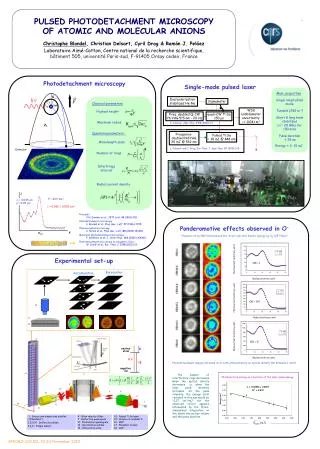
Interface Drawings SP Detector and DSS Placement of Detector Cryostat
Interface Drawings SP Detector and DSS Placement of Detector Cryostat. Farshid Feyzi 24 January 2019. Ouline. APA construction and assembly tolerances APA installation tolerances APA pitch, warm state and cold state CPA pitch warm state and cold state TPC position in cryostat

Interface Drawings SP Detector and DSS Placement of Detector Cryostat
E N D
Presentation Transcript
Interface Drawings SP Detector and DSS Placement of Detector Cryostat Farshid Feyzi 24 January 2019
Ouline • APA construction and assembly tolerances • APA installation tolerances • APA pitch, warm state and cold state • CPA pitch warm state and cold state • TPC position in cryostat • Need for interface drawings • Interface drawings DSS and TPC F. Feyzi
APA Pitch • APA design width is 2316.6 mm (note: APA#7 measurement is 2317.5 mm) • APA envelope width is 2324 mm to account for APA width tolerance and misalignment between upper and lower APA • APA active area width is 2300 mm • APA yoke centering tolerance ±1 mm (estimate) • DSS beam and hanger cumulative tolerance ±1 mm (estimate) • Set pitch at 2328 mm (note: ProtoDUNE pitch was 2320 mm) F. Feyzi
APA and CPA Pitch F. Feyzi
APA Motion from Warm to Cold State F. Feyzi
CPA Motion from Warm to Cold State F. Feyzi
Upper East Corner –TPC Centered F. Feyzi
Lower East Corner –TPC Centered F. Feyzi
Upper West Corner –TPC Centered F. Feyzi
Lower West East Corner –TPC Centered F. Feyzi
Plan View F. Feyzi
Interface Drawings • Need interface drawings at several stages in the integration process • They will be used as quality check for models • They must be unambiguous and verifiable by all design teams • Must not need to consult complex models to verify that design dimensions are compatible with interface drawings • It must be possible to verify dimensios on part production drawings F. Feyzi
Lateral Cross Section F. Feyzi
One Cell of TPC F. Feyzi
Upper Corner APA to CS Interface F. Feyzi
Lower Corner APA to CS Interface F. Feyzi
Middle APA Lower Interfacae F. Feyzi
Upper CPA Interface F. Feyzi
Lower CPA Interface F. Feyzi
Reference Frame of SP Detector • Need to define a reference frame • Will be used or placement of components and for alignment • How does it relate to cryostat? • Need to define coordinate system. F. Feyzi
Origin, Need to Decide F. Feyzi
Horizontal and Level Reference Plane- top of APA yoke F. Feyzi
Another Example of an Interface Drawing Obsolete F. Feyzi