Download
1 / 20
280 likes | 963 Views
Structural Steel Construction. Standard Structural Shapes. Standard Structural Shapes. Built up Girders. Structural Properties. American Institute of Steel Construction (AISC) Manual The Bible for Structural Steel Design……. Dimensions. W 14 X 500 Weight = 500 lbs per foot

E N D
Structural Properties American Institute of Steel Construction (AISC) Manual The Bible for Structural Steel Design……
Dimensions W 14 X 500 Weight = 500 lbs per foot Area = 147 in2 Depth = 19.60 in Web Thickness = 2.190” Flange Width = 17.010” Flange Thickness = 3.500”
Bolt Spacing Bolt gage lines: 1. Gage lines are lines along which bolts are placed. 2. Usually run parallel to the long axis of angles, beams and channels. • Gage distances (gage): • Distance between two gage lines if more than one row of bolts. • Distance from known edge of structural shape to a row of bolts. • Auxiliary gage distance (g1) is the distance needed to clear corner radii on structural shapes plus edge distance for mating part. • Pitch: • Distance between bolts along a gage line. • Minimum pitch is 3 times the diameter of the bolt. • Edge Distances: • Distance from edge of structural shape to center of bolt.
Bolt Spacing (continued) Minimum edge distances for ¾” bolts and larger: 1. For rolled edges: 1.25 times diameter of bolt. 2. For sheared edges: 1.5 times diameter of bolt.
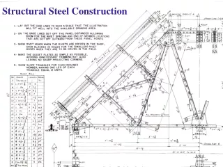
General Rules for Detailing • Use thin lines to draw detailed structural shape. If it is necessary to show adjoining parts of the structure use a very thin line to show the parts. • Dimensions lines are shown unbroken and the dimension is show at the top of the dimension line. All distances greater than twelve inches are shown in feet and inches. Decimals are not used. Architectural style units are used. • Dimensions should be placed as near the part as possible. At intersections there may be some overlapping of body and dimension lines, therefore, take great care in placing the dimensions to avoid confusion and make the dimensions easier to read. • When several dimensions are alike and adjacent, for example bolts the dimensions may be given by indicating the number of spaces times the distance on centers of bolts which equals the entire distance. For example: If there are five bolts spaced 2-1/2 on centers the dimension may be written as 4 spaces, at 2-1/2” = 10”.