Download
1 / 1
10 likes | 96 Views
This article details the development of a heterodyne receiver for Band 1 of the Atacama Large Millimeter Array (ALMA) in Chile. The construction includes components such as the horn, OMT, amplifiers, filters, and mixers to cover the 31.3-45 GHz range. Various design, simulation, and results of critical components are discussed, highlighting technological advancements to meet ALMA specifications.

E N D
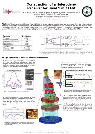
Construction of a Heterodyne Receiver for Band 1 of ALMAN. Reyes1, P. Zorzi1, F. P. Mena1, C.Granet2, E. Michael1, C. Jarufe, F. Colleoni, Francisco Navarrete, Rodrigo Pacheco, L. Bronfman3, and J. May31 Electrical Engineering Department, Universidad de Chile, Av. Tupper 2007, Santiago, Chile2 BAE Systems Australia Ltd, 40-52 Talavera Road, North Ryde 2113, Australia 3 Astronomy Department, Universidad de Chile, Camino El Observatorio 1515, Santiago, ChileContact: nireyes@ing.uchile.cl pmena@ing.uchile.cl Abstract: The Atacama Large Millimeter Array (ALMA) is the largest radio astronomical array ever constructed. Every one of its constituent antennas will cover the spectroscopic window allowed by the atmospheric transmission at the construction site with ten different bands. Despite being declared as a high scientific priority, Band 1 (31.3 45 GHz) was not selected for construction during the initial phase of the project. Universidad de Chile has recently started a program for the construction of a prototype receiver for band 1 of ALMA. Fig. 1. Layout of the receiver for band 1 of ALMA. The incoming RF signal is coupled with the horn via a lens (Sec. I). The signal is then divided in its polarization components in an OMT (Sec. II). Then, each polarization signal is amplified (Sec. III). Finally, the amplified signals are filtered to suppress the lower sideband (Sec. IV) and mixed in separate Schottky diodes (Sec. V). Design, Simulation and Results of critical components: I. The incoming signal is brought to a corrugated horn via a lens. A corrugated spline-profile horn was designed and tested. This horn has the advantage over traditional corrugated horns of being half of the size, keeping the main features almost unchanged. II. After the horn, the signal is divided in its linear polarization components using an orthomode transducer (OMT). We have scaled the OMT introduced by Asayama for band 4 [1]. Fig. 2. Transmission and reflection measurements results of our first prototype OMT constructed device. H denotes the horizontal polarization input mode of the received signal while the V stands for the vertical polarization mode. Fig. 1. : Spline-Line corrugated Horn radiation patterns simulation versus measurement results at 38 Ghz. IV. To avoid standing wave between active components isolators are used. We have selected cryogenic isolators from Channel microwave as they have a compact configuration. III. Each polarization branch is first amplified. We have developed LNAs based in commercial GaAs MMICs. To reach the ALMA specifications better technology is need. We have designed hybrid LNAs based in InP transistors. These amplifiers are under construction (2011). V. The amplified signal is filtered using a waveguide filter to suppress the image band. Then is down converted using commercial balanced mixer. This configuration allow the receiver to have an image rejection better than -20dB. Fig. 3. Measured S-Parameters of LNA v2.2. The average Noise over the Band 1 range is 3.0 dB (290K) at ambient temperature. We are currently working on a test setup for cryogenic measurement. This project is supported by the Center of Excellence in Astrophysics and Associated Technologies (PBF 06).