Download

1 / 24
240 likes | 262 Views
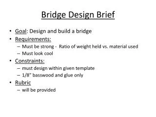
The bridge design by Oklahoma State University ASCE student chapter aimed to withstand 20kN load with minimal deflection. The bridge materials were carefully selected to ensure durability and weather resistance. The design process involved meticulous planning and execution to meet stringent performance criteria.

E N D
National Timber Bridge Design Competition - 2019 College or University Name: Oklahoma State University Student Chapter (ASCE or FPS): ASCE Address: Website Address: Faculty Advisor: Dr. Robert Emerson Email: robert.emerson@okstate.edu Phone: 405-334-143 Student Member in Charge of Project: Jay Joslin Email: jay.joslin@okstate.edu Phone: 580-271-0517
Hours Spent on This Project Students: 260 Faculty: 20 Cost of Materials Donated: $0 Purchased: $895
Abstract: The concept of this bridge design was to withstand a total load of 20kN, with a maximum deflection of 0.01m in the longitudinal direction, and 0.015m in the transverse direction. These loads will be distributed in four 5kN point loads. These loads will be 1m apart in the longitudinal direction, and 0.6m in the transverse direction. The bridge was designed to have a third of the maximum allowed deflection. The load being applied to the bridges surface will first be applied to the transversely laid bridge deck, which will be transferred to the plywood beneath. From the plywood, the load will be transferred to the eleven transverse beams. When applied to the transverse beams, around 10kN will be transferred to each longitudinal beam.
2. Deflection Table (Deflection – millimeters rounded to 2 decimal places) • Loading Increments • Bridge – As measured at midspan of the longitudinal beam receiving greatest loading. • Beam L – As measured under the longitudinal beam to left of selected deck monitoring point. • Beam R – As measured under the longitudinal beam to right of selected deck monitoring point. • Average (L & R) – Average of 3 and 4, above. • Gross Deck – As measured under the loading point expected to experience maximum deflection. • Net Deck – Column 6 minus Column 5. Deck Span: Transverse distance between main longitudinal bridge support members measured from inside edge to inside edge = ______1500_______mm ÷ 100 = ______15______mm = maximum allowable net deck deflection.
4. Summary – Describe Bridge and Its Behavior Under Load (max. 500 words) The bridge didn’t show any deformations on the side view or the box beams. The decking boards defected some due to them having uneven surface which could be from it some non perfect, non flush screws, or from warpage. The bridge held its shape and did not show signs that it was even being loaded.
Drawing Clearly Showing Location of Loading and Deflection Gage Points in Relation to Longitudinal Members (insert below)NOTE: Repeat slide if loading set-up was moved to measure deck deflection.
Drawing Clearly Showing Location of Loading and Deflection Gage Points in Relation to Transverse Members (insert below)NOTE: Repeat slide if loading set-up was moved to measure deck deflection.
PHOTO Showing SIDE View of Loading Setup for Measuring Bridge Deflection (insert below)NOTE: Repeat slide if loading set-up was moved to measure deck deflection.
PHOTO Showing END View of Loading Setup for Measuring Bridge Deflection (insert below)NOTE: Repeat slide if loading set-up was moved to measure deck deflection.
7. Preservative Treatment: Describe the preservative treatment applied to all wood members. Include type and concentrations. Also, include a short statement of why this treatment was selected. Did the treatment requirement present any special problems? If yes, provide details. If treatment was not selected, explain why. We chose to use pressure treated southern pine lumber. We made this choice to increase the weatherability of our bridge, its resistance to moisture, and therefore its lasting durability. This treatment did not present any issues aside from the associated higher cost of materials.
8. Special Considerations –Indicate the End Use of Your Bridge Our bridge will be left with the Oklahoma State University College of Civil Engineering to do with as they see fit. Typically bridge are put into use in front of the Bert Cooper Laboratory
9. Summarize the Team’s Experience from Participation in this Competition. Was it beneficial? What steps would you recommend to improve the experience? Our teams found this competition experience to be very beneficial. We all learned a lot about design using timber and the construction process. We also gained valuable team skills and improved our communication.
One photo of each deflection gauge at full loading, with identification sign indicating DECK, BEAM LEFT, BEAM RIGHT, BRIDGE. BEAM RIGHT BRIDGE DECK BEAM LEFT
Add as many photos as you wish showing the bridge construction process. Especially consider photos of internal structural components that may not be visible to judges from observing the finished bridge.