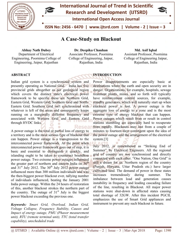
Slug Handling System on NQ Platform - A Case Study for C-Series Pipeline Offshore Engineering Services ONGC Ltd. Mumb
300 likes | 1.7k Views
Slug Handling System on NQ Platform - A Case Study for C-Series Pipeline Offshore Engineering Services ONGC Ltd. Mumbai Back Ground C - Series fields lie 60 km. West of Daman.

Slug Handling System on NQ Platform - A Case Study for C-Series Pipeline Offshore Engineering Services ONGC Ltd. Mumb
E N D
Presentation Transcript
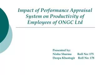
Slug Handling System on NQ Platform - A Case Study for C-Series PipelineOffshore Engineering ServicesONGC Ltd.Mumbai
BackGround • C - Series fields lie 60 km. West of Daman. • Comprises of mainly Gas bearing structures viz. C-39-8, C-39-6, C-39-1, C-26, C-24, C-23, C-22, B-12-7 and B-12-1. • Water depth variation 19m-30m. • Each structure has limited production capacity • Short production life.
Facilities to be created • The Scheme shall be completed in three phases : • Total Unmanned Well Platforms : 8 Nos. • Phase I - 4 ( C-22, C-24, C-39-1 & C-39-A) Phase I (except pipelines) commissioned in April 2009 • Phase II (5th Year) - 2 ( C-23 & B-12-7 ) • Phase III (11th Year) - 2 ( C-26 & B-12-1 )
Pipeline network for C-Series C-39-A C-39-1 Phase-I 8”X 2.5 km Phase-II 22” X 60 km C-39-A to C-24 C-23 Phase-III 8” X 3 km C-22 C-24 8” X 2.5 km 8” X 2 km C-26 B-12-1 C-24 to NQG 28” X 115 km 8” X 3 km 8” X 2 km B-12-7 Existing NQG Proposed Uran
Production Scenario(Peak Rate) Gas, MMSCMD Condensate, M3/HR • Phase I - 3.20 28.33 • Phase II (5th year) - 3.58 67.00
Brief Description of the Pipeline System C-Series pipeline is 175 km. long having diameter of 22” & 28” The pipeline starts from C-39-A and runs upto C-24 with a diameter of 22” and distance of 60 Km. The line further starts from C-24 and ends at NQG with a diameter of 28” and distance of 115 Km. Seabed on the pipeline route slopes down gradually from 20 m at C-series end to 60 m at NQG end The pipeline has been designed to transport 3.58 MMSCMD gas and 67 m3/hr condensate from the marginal fields to NQ process complex.
Slug Flow What is slug flow ? Slug flow is a two-phase flow pattern which is characterized by a sequence of packs of liquid separated by long gas bubbles flowing over a liquid film inside the pipe and is normally associated with high pressure-drops. How slug is formed ? Slug formation is a phenomenon which is normally observed in long distance pipelines having uneven terrain (called terrain sluging) and/ or pipeline id much higher than that required for normal through-put (called hydrodynamic slugging) Implications of slug flow on receiving facilities Unless sized appropriately, the slug flow may cause operational imbalance and even cause production loss or facilities’ shut down
Study Description A dynamic simulation of the pipeline was carried out through Scand Power Technology, Dubai using their Olga Software to ascertain the possibility of slugging of the pipeline under various operating scenario. The objective of the study were to determine the slugging of the pipeline under various operating scenario like reduced flow, shut down, re-start and production ramp-up.
Simulation Scenarios In order to optimise the number of simulations, following typical cases were simulated using Olga software. Constant production rates: Considering 25%, 50%, 75% and 100% of maximum production rates for Phase-I & Phase-II. Turn down Simulation: Reducing the production rates under Phase-II from 100% to 75%, 75% to 50%, 50% to 25% Shut-in Simulation: Shutting down the Production under Phase-II of each source simultaneously from 25% to non flowing condition. Re-start Simulation: Restarting the production from non-flowing condition to 25% and non-flowing condition to 100%. Ramp-up Simulation: Increasing the production from 25% to 50%, 50% to 75%, 75% to 100% and 25% to 100%.
Result of various scenarios simulated CONSTANT PRODUCTION RATES 1) It is observed that higher the production rate, lower is the liquid content in the pipeline. Mild terrain slugging was observed at upstream ends i.e. well heads, for 25% production rate for both, Phase-I and Phase-II. Maximum liquid content observed in the pipeline ( 2764 m3 in Phase-I and 3295 m3 in Ph-II). No slugging was observed at the downstream end at NQG and fluid arrival rate at NQG was found to be well within the handling capacity of NQG topside facilities. 4) Slug flow resulted in well head pressure fluctuations of approx. 1 bar. The slug frequency was approx. 1 slug per day for Phase-I and 2.8 slugs per day for Phase-II. Contd.
Result of various scenarios simulated (contd.) TURN DOWN SIMULATION It is observed that higher the turndown, higher is the time for liquid content to get stabilized. 265 hrs. (~11 days) are required for liquid content to get stabilized in 28” C-24-NQG pipeline when production rate is reduced from 100% to 25%. Whereas stabilization takes around 70 hrs. (~3 days) when production rate is reduced from 100% to 75%. No slugging was observed during the stabilization period for any turndown case.
Result of various scenarios simulated (contd.) SHUT IN SIMULATION It is observed that after the wellheads were shut-in for 11.5 hrs, the riser base towards NQG was completely filled up with liquid due to down slope geometry of the pipeline towards NQG. After 24 hours shut-in, the liquids had completely filled section from KP 110.63 to riser base having pipe volume 175 m3. Moreover, the pipe from KP 108.85 to KP 110.63 was partially filled accounted for 273 m3 liquid from KP 108.85 to the riser base. The liquid accumulation towards riser base at NQG gives rise to slug upon restart. It was also observed that higher the period of shutdown, higher is the volume of slug upon restart.
Result of various scenarios simulated (contd.) RESTART SIMULATION 1) Both 100% and 25% restart resulted in slug flow and were beyond the NQG handling capacity. Reduced restart flow rate does not have much impact except prolonging the arrival rate of slug. 2) Liquid slug was also followed by gas surge of magnitude much higher than the design capacity of the topside facilities. 3) For restart to 100% production case, the liquid rate surged to a peak value after 3 hours had passed since flow was resumed. The total liquid surge volume in excess of handling capacity (~100 m3/hr) was 269 m3 and the processing time required was 3 hrs. A gas surge of magnitude 16 MMSCMD (for a short duration) followed by liquid slug of 12758 m3/hr (for a short duration) was also observed. Subsequent surges were found to be within the handling capacity. Contd.
Result of various scenarios simulated (contd.) RESTART SIMULATION For restart to 25% production case, the liquid rate surged to a peak value after 9.3 hours had passed since flow was resumed. The total liquid surge volume in excess of handling capacity (~100 m3/hr) was 286 m3 and the processing time required was 3.5 hrs. A gas surge of magnitude 11 MMSCMD (for a short duration). followed by liquid slug of 16688 m3/hr (for a short duration) was also observed. A subsequent gas surge of equal magnitude was observed at10th hour. It is also observed that any shutdown greater than 1 hour will produce slug on restart. However, additional restart simulation is required to quantify the same. Contd
Result of various scenarios simulated (contd.) RESTART SIMULATION 6) Experienced velocities exceeding erosional velocity ratio by a factor of 1.1 in C-24 22” riser during 100% restart operation. However, erosional velocity limit was not exceeded in the pipeline network. 7) Experienced velocities exceeding erosional velocity ratio by a factor of 1.4 in C-24 22” riser during 25% restart operation. The average velocity did not exceed the erosional velocity limit but due to slug flow, the gas velocity instantaneously surged beyond the erosional velocity.
Result of various scenarios simulated (contd.) RAMP-UP SIMULATION Ramp-up in steps i.e. increasing the production from 25% to 50%, 50% to 75% and 75% to 100% allowing the flow to stabilize after each increment do not cause any slug flow at NQG. Such ramp-up from 25% flow rate to maximum production rate could be achieved in 3 days. The liquid surge for 25% to 100% ramp-up was found to be greatest volume of ramp-up surges analyzed. The liquid surge volume produced was in excess of NQG handling capacity. During 25% to 100% ramp-up, erosional velocity limit was exceeded for few segments of pipeline network. During sequential ramp-up, erosional velocity limit was only exceeded in C-24 22” riser.
Recommendations for possible remedial measures Increasing handling capacity leading to reduction in time required to process liquid surges. Implementation of topside choke leading to reduction in surge volumes within the current vessel volumes and handling capacity rates.
Implementation of the Scheme Since the platform facilities have already been put in place, any addition of facilities for increasing capacity would involve time and cost. This would result in delay in commissioning the plant or shutdown for long duration. Containing the surge flow at the inlet with choke / control valve for the duration that the surge is anticipated is most reasonable solution to the problem. The P&ID (Piping and Instrumentation Diagram) of the process before the slug control scheme is implemented is shown in the next slide.
Implementation of the Scheme (contd.) A combination of the shutdown valve and control valve on the bypass line would ensure safe operation during the start-up of the line after a shutdown. 6” control valve has been found suitable for the control of the slug flow and intermittent gas flow. Any lower size would become a constraint for the quantity of the gas flow envisaged intermittently during the slug flow. In addition, inlet shutdown valve is provided upstream of control valve to shutdown facilities during for upset condition during slug flow.
Implementation of the Scheme The 6” SDV shall be opened manually for START-UP at site. (The control valve is kept crack open during this activity). The 24” SDV will remain in closed condition during slug flow until it is safe to open for normal operation once the slug is cleared. To ensure above, independent local pneumatic selector “pull-in / reset”’ type 3-way selector valve is provided for both SDVs. Once the slug flows ceases, 24” SDV shall be opened and then 6” SDV shall be closed. Schematic for manual selection of the SDV is shown in next slide.
Implementation of the Scheme – Control Valve The 6” Control Valve has a ’Hand wheel’ for on site manual operations of the valve if necessary. Operation of the control valve can be done from control room, using the Controller being provided for this valve. Manual or Auto operation mode is operator selectable. To begin with, the operation of start up is envisaged to be manual with a pre determined Crack opening (up to 20% opening). Once the line pressure starts dropping from 26 kg/cm2g to 11 kg/cm2g, the valve may be opened further gradually over a period of time and level of KOD downstream is continuously monitored alongwith inlet pressure. The KOD has its own level controller which shall maintain the KOD level. When there is liquid inflow (Slug) which is more than the valve can handle, (i.e. LCV full open), the operator shall start to close the SCV gradually to reduce inflow and maintain the KOD level.
Implementation of the Scheme – Control Valve (contd.) FEEDBACK CONTROL METHODS SSIC shall keep the SCV sufficiently open to allow 80 M3 /Hr flow to maintain KOD level stable. This opening (%) will be known better with experience over a period of time. The level controller (LIC) for KOD level control (Condensate level) is utilized for determining the operation of the SCV in feed back mode. LIC output shall become PV (Process Variable) for the SSIC. Set point of SSIC shall be set at a value in the range 75 to 80% (i.e. 16 to 17mA in 4-20mA). Any increase in the PV value of SSIC beyond this shall start to close SCV. SSIC shall keep SCV open for all PV values up-to the SET-POINT value.
Implementation of the Scheme – Control Valve (contd.) Alternately, LT output (KOD level) can be used as PV (Process Variable) for SSIC. Set point is set at a value in the range 75 to 80% (i.e. 16mA to 17mA in 4-20mA). Any increase in the PV value of SSIC beyond this shall start to close SCV.
Conclusion It is observed that the adopted method of slug control for maintaining KOD level is most appropriate as it is not dependent on complicated software which use assumed conditions and predictive methods for slug control.