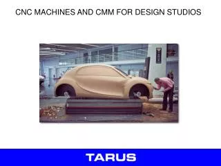
NC and CNC machines and Control Programming
NC and CNC machines and Control Programming. Introduction to NC and CNC machines CNC controls and RS274 programming. History of CNC. 1949 US Air Force asks MIT to develop a "numerically controlled" machine. 1952 Prototype NC machine demonstrated (punched tape input). 1980-

NC and CNC machines and Control Programming
E N D
Presentation Transcript
NC and CNC machines and Control Programming Introduction to NC and CNC machines CNC controls and RS274 programming
History of CNC 1949 US Air Force asks MIT to develop a "numerically controlled" machine. 1952 Prototype NC machine demonstrated (punched tape input) 1980- CNC machines (computer used to link directly to controller) 1990- DNC: external computer “drip feeds” control programmer to machine tool controller
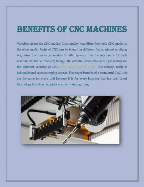
Motivation and uses To manufacture complex curved geometries in 2D or 3D was extremely expensive by mechanical means (which usually would require complex jigs to control the cutter motions) Machining components with repeatable accuracy Unmanned machining operations
Advantages of CNC - Easier to program; - Easy storage of existing programs; - Easy to change a program - Avoids human errors - NC machines are safer to operate - Complex geometry is produced as cheaply as simple ones - Usually generates closer tolerances than manual machines
Conventional milling machines Vertical milling machine
Conventional milling machines Vertical Milling machine architecture
Conventional milling machines Horizontal Milling machine architecture How does the table move along X- Y- and Z- axes ?
NC machines Motion control is done by: servo-controlled motors
CNC terminology BLU: basic length unit smallest programmable move of each axis. Controller: (Machine Control Unit, MCU) Electronic and computerized interface between operator and m/c Controller components: 1. Data Processing Unit (DPU) 2. Control-Loops Unit (CLU)
Controller components Data Processing Unit: Input device [RS-232 port/ Tape Reader/ Punched Tape Reader] Data Reading Circuits and Parity Checking Circuits Decoders to distribute data to the axes controllers. Control Loops Unit: Interpolator to supply machine-motion commands between data points Position control loop hardware for each axis of motion
Types of CNC machines Based on Motion Type: Point-to-Point or Continuous path Based on Control Loops: Open loop or Closed loop Based on Power Supply: Electric or Hydraulic or Pneumatic Based on Positioning System Incremental or Absolute
Open loop control of a Point-to-Point NC drilling machine NOTE: this machine uses stepper motor control
Components of Servo-motor controlled CNC Motor lead screw rotation table moves Motor speed control feedback position sensed by encoder Two types of encoder configurations
Motion Control and feedback Encoder outputs: electrical pulses (e.g. 500 pulses per revolution) Rotation of the motor linear motion of the table: by the leadscrew The pitch of the leadscrew: horizontal distance between successive threads One thread in a screw single start screw: Dist moved in 1 rev = pitch Two threads in screw double start screw: Dist moved in 1 rev = 2* pitch
Example 1 A Stepping motor of 20 steps per revolution moves a machine table through a leadscrew of 0.2 mm pitch. (a) What is the BLU of the system ? (b) If the motor receives 2000 pulses per minute, what is the linear velocity in inch/min ?
Example 2 A DC servo-motor is coupled to a leadscrew (pitch 5mm) of a machine table. A digital encoder, which emits 500 pulses per revolution, is mounted on the leadscrew. If the motor rotates at 600 rpm, find (a) The linear velocity of the table (b) The BLU of the machine (c) The frequency of pulses emitted by the encoder.
Manual NC programming Part program: A computer program to specify - Which tool should be loaded on the machine spindle; - What are the cutting conditions (speed, feed, coolant ON/OFF etc) - The start point and end point of a motion segment - how to move the tool with respect to the machine. Standard Part programming language: RS 274-D (Gerber, GN-code)
History of CNC The RS274-D is a word address format Each line of program == 1 block Each block is composed of several instructions, or (words) Sequence and format of words: N3 G2 X+1.4 Y+1.4 Z+1.4 I1.4 J1.4 K1.4 F3.2 S4 T4 M2 destination coordinates dist to center of circle tool sequence no spindle speed feed rate preparatory function miscellaneous function
Manual Part Programming Example Tool size = 0.25 inch, Feed rate = 6 inch per minute, Cutting speed = 300 rpm, Tool start position: 2.0, 2.0 Programming in inches Motion of tool: p0 p1 p2 p3 p4 p5 p1 p0
1. Set up the programming parameters Programming in inches Use absolute coordinates Feed in ipm N010 G70 G90 G94 G97 M04 Spindle speed in rpm Spindle CCW
2. Set up the machining conditions Machine moves in XY-plane Use full-circle interpolation Feed rate Spindle speed N020 G17 G75 F6.0 S300 T1001 M08 Tool no. Flood coolant ON
3. Move tool from p0 to p1 in straight line Linear interpolation target coordinates N030 G01 X3.875 Y3.698
4. Cut profile from p1 to p2 Linear interpolation target coordinates N040 G01 X3.875 Y9.125 or N040 G01 Y9.125 X-coordinate does not change no need to program it
5. Cut profile from p2 to p3 Linear interpolation target coordinates N050 G01 X5.634 Y9.125
6. Cut along circle from p3 to p4 circular interpolation, CCW motion target coordinates N060 G03 X7.366 Y9.125 I6.5 J9.0 coordinates of center of circle
7. Cut from p4 to p5 Linear interpolation target coordinates (Y is unchanged) N070 G01 X9.302
8. Cut from p5 to p1 Linear interpolation target coordinates (see step 3) N080 G01 X3.875 Y3.698
9. Return to home position, stop program Linear interpolation target coordinates (see step 3) N090 G01 X2.0 Y2.0 M30 end of data N100 M00 program stop
Automatic Part Programming Software programs can automatic generation of CNC data Define Tool CNC data Make 3D model Simulate cutting
Automatic part programming and DNC Very complex part shapes very large NC program NC controller memory may not handle HUGE part program computer feeds few blocks of NC program to controller When almost all blocks executed, controller requests more blocks
Summary CNC machines allow precise and repeatable control in machining CNC lathes, Milling machines, etc. are all controlled by NC programs NC programs can be generated manually, automatically Additional references: RS274D code descriptions