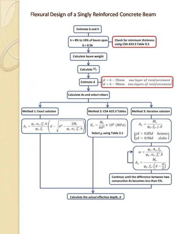
Flexural Beam Bending
Flexural Beam Bending. EE485A Lecture 10 September 2009. Mass-Spring Systems. k = 1 N/m. k = 1 N/m. k = 1 N/m. k = 1 N/m. 1 kg. 1 kg. k = 1 N/m. 1 kg. Given that gravity is acting on these masses, how far will each of these masses deflect?. Springs are everywhere.

Flexural Beam Bending
E N D
Presentation Transcript
Flexural Beam Bending EE485A Lecture 10 September 2009
Mass-Spring Systems k = 1 N/m k = 1 N/m k = 1 N/m k = 1 N/m 1 kg 1 kg k = 1 N/m 1 kg Given that gravity is acting on these masses, how far will each of these masses deflect?
Springs are everywhere • Mass-spring systems ubiquitous in MEMS • Goal for today: to derive the spring constant for a MEMS beam from its geometry and material properties.
Beam Boundary Conditions • Beams are classified according to their supports
Identifying Boundary Conditions Fixed-fixed bridges (b,c*,f,h*) Fixed-free cantilevers (a,d,e,g,i,j) Four fixed-guided beams connect to rigid shuttle (k)
Pure Bending • Defined as when the moment is constant throughout the beam • Upper part of the beam is shortened and is in compression • Lower part of the beam is lengthened and is in tension • Neutral plane is dividing line, defined as surface with no longitudinal change in length.
y F Strain-Curvature Relation dq x y=0 The strain and stress vary through the thickness of the beam– they are greatest at its farthest distance from the neutral axis! Length of segment before bending: dx Length of segment after bending: dx - yk Strain curvature relation: sx = -ky
Normal stresses in beams y Elemental bending moment: sx Integrating to find total moment M x Leads to Beam Equation:
Calculating the moment of inertia Really the “second moment or inertia” or “second moment of area” For applying these equations, y is in the direction that the beam is bending. t w Prove:
Orientation matters • Determine the proper moments of inertia to use for the case of force F1 and force F2 F1 1 m 10 m F2
Deflection of Beams F x y New definition to y and x, treating beam as thin sheet at neutral axis plane
F Example Prove that deflection, y, at point x is given by: Prove that the tip deflection, ymax, is given by:
F Finding spring constants • Use the relation between the Force and tip displacement to determine the effective spring constant for the beam. Effective Spring Constant, k
A Practical Application A simplified silicon accelerometer is shown below, which is designed to detect acceleration in the –y direction. For silicon, E = 130 GPa, density = 2300 kg/m3 Force direction t = 1 mm W = 10 mm H = 10 mm L = 200 mm • Determine the spring constant of the beam. • Determine how far the tip mass will move if the sensor encounters an acceleration of 100g. • How could you make this device more sensitive? (More deflection for the same acceleration)