Download
1 / 39
390 likes | 487 Views
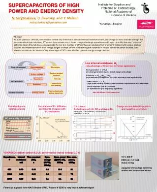
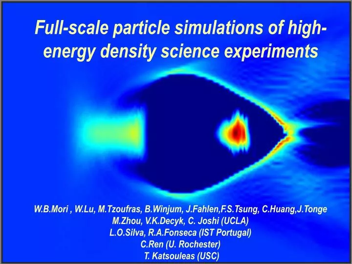
Full-scale particle simulations of high-energy density science experiments W.B.Mori , W.Lu, M.Tzoufras, B.Winjum, J.Fahlen,F.S.Tsung, C.Huang,J.Tonge M.Zhou, V.K.Decyk, C. Joshi (UCLA) L.O.Silva, R.A.Fonseca (IST Portugal) C.Ren (U. Rochester) T. Katsouleas (USC).

E N D
Full-scale particle simulations of high-energy density science experiments W.B.Mori , W.Lu, M.Tzoufras, B.Winjum, J.Fahlen,F.S.Tsung, C.Huang,J.Tonge M.Zhou, V.K.Decyk, C. Joshi (UCLA) L.O.Silva, R.A.Fonseca (IST Portugal) C.Ren (U. Rochester) T. Katsouleas (USC)
Directed high-energy density Lasers Particle beams • Pressure=Energy/Volume • Pressure=Power/Area/c • PetaWatt with 10mm spot • 3x10¹⁰ J/cm3 • 300 GBar • Electric field in laser: • TeV/cm • At SLAC: • N=2x10¹⁰ e- or e+ sr=1mm, sz =60mm • E=50GeV • Pressure: • 15x1010J/cm3 • 1.5TBar • Electric field of beam: • 1.6TeV/cm
Radiation pressure and space forces of intense lasers and beams expel plasma electrons Beam driver Laser driver Laser driver
Particle AcceleratorsWhy Plasmas? Conventional Accelerators Plasma • Limited by peak power and breakdown • 20-100 MeV/m • No breakdown limit • 10-100 GeV/m Why lasers? Radiation pressure can excite longitudinal wakes
Concepts For Plasma Based Accelerators* • Plasma Wake Field Accelerator(PWFA) • A high energy electron bunch • Laser Wake Field Accelerator(LWFA, SMLWFA, PBWA) • A single short-pulse of photons • Drive beam • Trailing beam Wake excitation Evolution of driver and wake Loading the wake with particles *Tajima and Dawson PRL 1979
Plasma Accelerator Progress and the “Accelerator Moore’s Law” Slide 2 LOA,RAL LBL ,RALOsaka Courtesy of Tom Katsouleas
The blowout and bubble regimesRosenzwieg et al. 1990 Puhkov and Meyer-te-vehn 2002Ion column provides ideal accelerating and focusing forces Trajectory crossing Beam driver Laser driver
Full scale 3D particle-in-cell modeling is now possible:OSIRIS Typical simulation parameters: ~109 particles ~105 time steps Other codes:VLPL, Vorpal, TurboWAVE, Z3 etc., but no all the same!
Progress in computer hardware The “Dawson” cluster at UCLA: <$1,000,000 $50,000,000
Progress in lasers Courtesy of G.Mourou
Progress in hardware and software • Era Memory particles speed max energy (full PIC) • 80’s 16MByte 105-106 5ms/part-step 100 MeV (2D) • Today ~6TByte/3 ~109 1x10⁻³ms/part-step 1-10GeV (3D (e.g., NERSC)(~7.5 Tflops/3) • Local ~500GByte~109 2x10⁻³ms/part-step1-10GeV (3D) • Clusters (2.3Tflops) 1 TeV (3D) • (e.g., DAWSON) • Future25-1000TByte>1011 5x10⁻⁵ms/part-step 500 GeV (3D) • 150Tflops - 10Pflops? The simulations of Tajima and Dawson would take ~1 second on my laptop!
Computational challenges for modeling plasma-based acceleration(1 GeV Stage)
Full-scale modeling:Challenges and expectations Challenges: What is excellent agreement? • As a laser propagates through the plasma it encounters ~1013-1014 electrons • There are ~106-109 self-trapped electrons • Need to model accuracy of 1 part in O(106) • Don’t know exact plasma profile. • Don’t know laser intensity or spot size. • Don’t know laser transverse, longitudinal, or frequency profile (not a diffraction limited Gaussian beam).
Convergence of advances in laser technology and computer simulation
State-of- the- art ultrashort laser pulse 0 = 800 nm, Dt = 50 fs I = 2.5x10¹⁸ W/cm-2, W =12.5 mm 512 cells 100 mm 512 cells 100 mm 2340 cells 56.18 mm Full scale 3D LWFA simulation using OSIRIS:6TW, 50fs • Simulation Parameters • Laser: • a0 = 1.1 • W0=15.6 l=12.5 mm • wl/wp = 10 • Particles • 2x1x1 particles/cell • 500 million total • Plasma length • L=.2cm • 50,000 timesteps Laser propagation Plasma Background ne = 2x1019 cm-3 Simulation ran for 6400 hours on DAWSON (~4 Rayleigh lengths)
Simulations: no fitting parameters! Nature papers, agreement with experiment 3D Simulations for: Nature V431, 541 (S.P.D Mangles et al) • In experiments, the # of electrons in the spike is 1.4 108. • In our 3D simulations, we estimate of 2.4 108 electrons in the bunch.
Movie of Imperial Run Plasma density and laser envelope
Experiment PIC 3D PIC simulations: Tweak parameters Propagation: 2 mm • Scenario: • self-focusing (intensity increases by 10) • longitudinal compression • Excite highly nonlinear wakefield with cavitation: bubble formation • trapping at the X point • electrons dephase and self-bunch • monoenergetic electrons are behind • the laser field Parameters: E=1 J, 30 fs, 18 µm waist, 6×1018 cm-3
State-of- the- art ultrashort laser pulse 0 = 800 nm, Dt = 30 fs I = 3.4x10¹⁹ W/cm-2, W =19.5 mm 256 cells 80.9 mm 256 cells 80.9 mm 4000 cells 101.9 mm Full scale 3D LWFA simulation using OSIRISPredict the future: 200TW, 40fs • Simulation Parameters • Laser: • a0 = 4 • W0=24.4 l=19.5 mm • wl/wp = 33 • Particles • 2x1x1 particles/cell • 500 million total • Plasma length • L=.7cm • 300,000 timesteps Laser propagation Plasma Background ne = 1.5x1018 cm-3 Simulation ran for 75,000 hours on DAWSON (~5 Rayleigh lengths)
OSIRIS 200 TW simulation: Run on DAWSON Cluster A 1.3 GeV beam! The trapped particles form a beam. • Normalized emittance:The divergence of the beam is about 10mrad. • Energy spread: Beam loading
Physical picture Evolution of the nonlinear structure • The blowout radius remains nearly constant as long as the laser intensity doesn’t vary much. Small oscillations due to the slow laser envelope evolution have been observed. • Beam loading eventually shuts down the self injection. • The laser energy is depleted as the accelerating bunch dephases. The laser can be chosen long enough so that the pump depletion length is longer than the dephasing length.
QuickPIC loop: 2-D plasma slab Wake (3-D) Beam (3-D): Laser or particles
QuickPIC: Basic concepts Solved by 2D field solver Maxell’s equations in Lorentz gauge Particle pusher(relativistic) Full PIC (no approximation) QuickPIC
e- driver e+ driver e- driver with ionization laser driver QuickPIC Benchmark: Full PIC vs. Quasi-static PIC Benchmark for different drivers • Excellent agreement with full PIC code. • More than 100 times time-savings. • Successfully modeled current experiments. • Explore possible designs for future experiments. • Guide development on theory. 100+ CPU savings with “no” loss in accuracy
A Plasma Afterburner (Energy Doubler) Could be Demonstrated at SLAC 0-50GeV in 3 km 50-100GeV in 10 m! 3 km 30 m Afterburners S. Lee et al., Phys. Rev. STAB, 2001
Excellent agreement between simulation and experiment of a 28.5 GeV positron beam which has passed through a 1.4 m PWFA OSIRIS Simulation Prediction: Experimental Measurement: Peak Energy Loss 64 MeV 65±10 MeV Peak Energy Gain 78 MeV 79±15 MeV OSIRIS E162 Experiment Head Tail Head Tail 5x10⁸ e+ in 1 ps bin at +4 ps
+4 +2 Relative Energy (GeV) 0 -2 -4 -5 0 +5 X (mm) Full-scale simulationof E-164xx is possible using a new code QuickPIC • Identical parameters to experiment including self-ionization: Agreement is excellent!
Full-scale simulationof E-164xx is possible using a new code QuickPIC
Full-scale simulation of a 1TeV afterburner possible using QuickPIC 5000 instead of 5,000,000 node hours • We use parameters consistent with the International Linear Collider “design” • We have modeled the beam propagating through ~25 meters of plasma.
I see a day where the world is fueled by fusion energy. I see a day where particle simulations will use 1 trillion particles I see a day when high energy accelerators will fit on a tabletop.
Wakefield equations:“2D-electro and magneto-statics Maxwell equations in Lorentz gauge Reduced Maxwell equations Quasi-static approx. We define Antonsen and Mora 1997 Whittum 1997 Huang et al., 2005 (QuickPIC)
2D loop end 2D loop begin 3D loop end 3D loop begin Initialize beam Initialize plasma Field Solver Maxwell equations in Lorentz gauge Call 2D routine Reduced Maxwell equations Push beam particles Push plasma particles Iteration Deposition Deposition Quasi-static Model including a laser driver Laser envelope equation:
beam Initial plasma slab 1 2 3 4 beam Initial plasma slab 1 2 3 4 solve plasma response solve plasma response solve plasma response solve plasma response solve plasma response update beam update beam update beam update beam update beam Without pipelining: Beam is not advanced until entire plasma response is determined With pipelining: Each section is updated when its input is ready, the plasma slab flows in the pipeline. Pipelining: scaling quasi-static PIC to 10,000+ processors
LWFA - Accelerating Field • Isosurface values: • Blue : -0.9 • Cyan: -0.6 • Green: -0.3 • Red: +0.3 • Yellow: +0.6 • Electric Field in normalized units me c wp e-1 512 cells 40.95 mm
After 5 Zr / 7.5 mm Total charge = 1.1 nC Simulations The 200 TW run: Dephasing ~ Pump depletion Given a we pick the density and we evaluate from our formulas: Laser plasma
Physical picture of an “optimal” regime Geometry - fields • The ponderomotive force of the laserpushes the electrons out of the laser’s way. • The particles return on axis after the laser has passed. • The region immediately behind the pulse is void of electrons but full of ions. • The result is a sphere (bubble) moving with the speed of (laser) light, supporting huge accelerating fields.
Physical picture Evolution of the nonlinear structure • The front of the laser pulse interacts with the plasma and loses energy. As a result the front etches back. • The shape and size of the accelerating structure slightly change. • Electrons are self-injected in the plasma bubble due to the accelerating and focusing fields. • The trapped electrons make the bubble elongate.
PIC Simulations of beam loading in blowout regime: Used the new code QuickPIC (UCLA,USC,U.Maryland) Bi-Gaussian shape z= 1.2 c/p, nb/np= 26 Wedge shape w/ beam load beam length = 6 c/p, nb/np= 8.4, Ndrive = 3x10¹⁰, Ntrailing = 0.5x10¹⁰