Download
1 / 33
330 likes | 555 Views
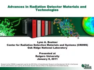
Advances in Radiation Detector Materials and Technologies. Lynn A. Boatner Center for Radiation Detection Materials and Systems (CRDMS) Oak Ridge National Laboratory Presented at Rutgers University January 8, 2011.

E N D
Advances in Radiation Detector Materials and Technologies Lynn A. Boatner Center for Radiation Detection Materials and Systems (CRDMS) Oak Ridge National Laboratory Presented at Rutgers University January 8, 2011 Research at the CRDMS is supported in part by the DOE Office of Nonproliferation Research and Development, NA-22, in the Nuclear Security Administration and in part by the Domestic Nuclear Detection Office of the Department of Homeland Security.
Radiation Detection by Scintillators or Electronic Materials Scintillator Detector Photomultiplier Incident Radiation Si Photodiode Eye IncidentRadiation Light Output (usually visible to near visible) SCINTILLATION DETECTION ELECTRONIC DETECTION
Gamma-Ray Scintillators • 3 Major Processess: • ABSORPTION OF GAMMA- OR X-RAY PHOTONS AND CONVERSION INTO CHARGED PARTICLES (ELECTRON-HOLE PAIRS). • Direct process: for E> 1.02 MeV the gamma ray directly produces an electron-positron pair with the same total energy (pair production). • Compton scattering: gamma-ray energy is divided between a scattered photon and a recoil electron • Photoelectric effect: the absorbed photon generates a fast electron and a hole in a deep core level of an ion with the two carrying all of the energy of the original photon. • ENERGY TRANSFER FROM THE ELECTRONIC EXCITATIONS TO THE LUMINESCENCE CENTERS. • A complex and not well-understood process. • EMISSION OF THE SCINTILLATION PHOTONS: • Occurs with a quantum efficiency Q that represents the fraction of excited centers that actually emit a scintillation photon.
γ β S L Q hυ -Ray Detection Using a Scintillation Crystal Requirements for a Good Scintillator 1. High Light Output (Photons/Mev) NaI: Thallium 38,000 BGO 8,200 2. Short Decay Time (Nano Sec) 3. Wavelength Match to Detector 4. High Density (>6 g/cm3) 5. Chemical Stability 6. Radiation Hardness 7. Cost 8. Crystal Growth NaI: Thallium 1948, Hufstader BGO (Bi4Ge3O12) 1973, Weber & Monchamp LSO (Lu2SiO5) 1992, Melcher & Schweitzer β-ray to electronic excitation S fraction transferred to luminescence centers Q quantum efficiency of the emission step http://scintillator.lbl.gov/
Among the alkaline earth halides, Strontium Iodide (Eu) possesses the most promising characteristics Advantages: •Low melting point → reduced temperature gradients •Size and structure match between SrI2 and EuI2 →unity distribution coefficient •High light yield, proportional → superior resolution •Congruent, since binary compound → no compositional gradients •Near-UV emission → ideal match to PMT response •Microsecond decay → enlarges dynamic range for pulse height spectrum
A New Grain Selector A new grain-selector geometry has been incorporated into the 2.5” OD Bridgman growth ampoules since it was found that two grains would sometimes propagate into the large-diameter growth chamber during the growth process – even the case of long straight grain selectors that incorporated a bulb configuration. Similar grain-selector geometries are uses in the growth of the metal and alloy single crystals – including single crystal high-performance-alloy turbine blades – for nucleation suppression.
Strontium Iodide Eu2+ Crystal Growth Enlarged view of the quartz frit that is used to filter the molten SrI2:Eu2+ salt that then flows into the Bridgman ampoule prior to sealing under vacuum.
Two-inch diameter single crystal of SrI2(Eu) grown at Oak Ridge National Laboratory.
Crystal 68f (Fisk University) was encapsulated in a standard aluminum can, and its performance is equivalent to the best RMD crystal.
Cs2LiYCl6 Cs2LiLaCl6 Cs2LiLaBr6 CLYC CLLC CLLB Elpasolites • High light yield 70,000 to 180,000 ph/neutron • High gamma equivalent >= 3 MeV • High energy resolution 2-3% • Pulse height discrimination • Pulse shape discrimination • Cubic structure www.rmdinc.com a dynasil member company
Summary of Properties www.rmdinc.com a dynasil member company
Melt zone Solidification zone Bridgman Grown Crystals 1 in CLYC 1 in CLLC CLLB www.rmdinc.com a dynasil member company
CLYC: 6Li vs. natLi Enrichment significantly improves detection of thermal neutrons. www.rmdinc.com a dynasil member company
Investigations of alternate methods for growing large single crystals of rare-earth halide scintillators from organic solutions have led to the discovery of a new metal-organic scintillator crystal. This new scintillator material is a methanol adduct of cerium trichloride with the formula: CeCl3(CH3OH)4. Large transparent single crystals of this material were grown from a seeded anhydrous methanol solution in a controlled-temperature bath, and the molecular structure was subsequently determined by single-crystal x-ray structure analysis. The CeCl3(CH3OH)4 metal-organic scintillator is applicable to x-ray, gamma-ray, alpha-particle, and neutron detection, and this new finding offers the promise of identifying other similar metal-organic molecular systems that offer the potential for serving as efficient radiation detector materials that can potentially be grown in large sizes using solution-growth methods. Most recently the scintillator La(4%Ce)Br3(CH3OH)4 has been discovered. New Metal-Organic Scintillators
Crystal Structure Perspective view of the CeCl3(CH3OH)4 adduct showing the bridging role of the chlorine atoms. The basic CeCl3(CH3OH)4 crystal data resulting from the single crystal x-ray structural refinement are: M = 374.64, monoclinic structure, space group P21/c (no. 14), a = 8.7092(5), b = 18.5100(9), c = 8.2392(4) Å, β = 108.946(1)°, V = 1256.2(1) Å3, Z = 4, and Dcalc = 1.981 g/cm3.
Large faceted single crystal of CeCl3(CH3OH)4 grown from an anhydrous methanol solution - shown on a cm scale. The platinum wires used to hold the seed crystal on the growth platform are visible through the crystal. Crystal growth was allowed to continue for a total growth time of 24 hrs - at which time the crystals were removed from the vessel, rinsed clean of the solution in fresh anhydrous methanol, dried, and sealed under dry inert gas.
Energy Spectra Energy spectrum of the CeCl3(CH3OH)4 metal-organic scintillator single crystal obtained using 662 keV gamma rays from a 137 Cs 1 Curie source. The light yield is ~ 230% of that of a BGO reference crystal - yielding a light yield of ~16,600 photons/MeV without corrections for the photomultiplier tube efficiency. The energy resolution was determined to be 11.4% for this specimen.
X-ray Luminescence X-ray-excited luminescence spectrum for a single crystal of CeCl3(CH3OH)4 measured in both transmission and reflection geometries using an x-ray tube operated at 35 kV as an excitation source. The peak of the luminescence occurs at ~ 365 nm.
Transparent Polycrystalline Ceramic ScintillatorsGlass Scintillators Why would we want these? Single crystal growth is a time-consuming, expensive, and rate-limiting process. Transparent polycrystalline ceramic scintillators and glass scintillators offer an alternative approach to scintillator synthesis that eliminates single crystal growth.
Lu2O3:Eu • Synthesis and Post Synthesis Treatment • Lu2O3 and Eu2O3 (5 wt. %) powders combined physically • Powder heated in vacuum to dry • Hot pressed at 1530°C with 262 kg/cm2 of pressure • Annealed with flowing oxygen for 72 hours at 1050°C Photograph of a Lu2O3:Eu ceramic before (right) and after (left) annealing in an oxygen atmosphere. Hot pressing technique tends to draw oxygen out of the host lattice, creating a dark color in the densified body. This coloration can be removed by annealing in an O2. Photograph of a Lu2O3:Eu ceramic excited by a 30kV continuous X-ray source. Photographs of a transparent Lu2O3:Eu ceramic (~1mm thick)
LSO:Ce • Synthesis and Post-synthesis Treatment • High quality LSO:Ce powder produced by Nichia Corporation (Japan) used • Powder heated in vacuum to dry • Hot pressed at 1400°C with 337 kg/cm2 of pressure for 2 hours • Annealed in vacuum at 1050°C/108h • Annealed in water vapor at 1050°C/32h • Annealed in air at 1150°C/32h Photograph of a LSO:Ce ceramic before (left) and after (right) annealing in vacuum Photograph of an LSO:Ce ceramic (0.6 mm thick). Note that no back-light is used in this photograph. Transmission electron microscopy (TEM) image of LSO:Ce powder from Nichia Corporation Scanning electron microscopy (SEM) image of LSO:Ce powder from Nichia Corporation. Particle size distribution of the Nichia LSO:Ce powder used to make the LSO ceramic.
Scintillating pulse shape of a LSO:Ce polycrystalline ceramic excited by 662 KeV gamma photons. The solid line represents single- and three-exponential (+ noise) fits to the experimental data . The decay time constants and contribution of faster components in comparison to the decay time of about 42 ns generally accepted for single crystal LSO. Energy spectra (for 662 keV excitation photons) of the LSO:Ce refernce crystal (the light yield for this crystal was ~30,000 photons/MeV) and the LSO:Ce ceramic at various post-sintering annealing stages. Symbol “A” denotes a ceramic with a 2 mm thickness after annealing in vacuum, “A1” denotes a 0.7 mm thick piece of the former ceramic after additional annealing in water vapor, and “A1a” the same after additional annealing in air.
New scintillators for gamma ray spectroscopy developed for DHS and DOE. (upper left) SrI2(Eu) single crystal under UV excitation, (upper right) GYGAG(Ce) ceramic, (bottom) two Bi-loaded polymers under UV excitation. Comparative Gamma Spectroscopy with SrI2(Eu), GYGAG(Ce) and Bi-loaded Plastic Scintillators N.J. Cherepy, Member, IEEE, S.A. Payne, Member, IEEE, B.W. Sturm, Member, IEEE, J.D. Kuntz, Z.M. Seeley, B.L. Rupert, R.D. Sanner, O.B. Drury, T.A. Hurst, S.E. Fisher, M. Groza, L. Matei, A. Burger, Member, IEEE, R. Hawrami, Member, IEEE, K.S. Shah, Member, IEEE, and L.A. Boatner IEEE Transactions on Nuclear Science, IEEE/NSS Proceedings 2010 (Submitted for publication)
GLASS SCINTILLATORSHOW CAN WE IMPROVE THEIR PERFORMANCE?Glass Scintillator Parameter Space Composition (Glass-forming space) Cladding Phosphate Lead Phosphate Silicate Germanate Arsenate … Activation Ce,Pr,Nd,Eu,Tb,Yb Co-doping Structure * Phosphate glass only Phosphate chain length Post-synthesis Treatment Time Temperature Atmosphere * B. C. Sales, J. O. Ramey, L. A. Boatner, and J. C McCallum, “Structural in equivalence of the Ion-Damaged-Produced Amorphous State and the Glass State in Lead Pyrophosphate,” Phys. Rev. Lett. 62, (10) 1138-1141 (1989).
Energy Spectra of Ce Doped Ca-Na Phosphate Glasses 137Cs 1μCiγ source 662 keVγ photons 0.5 μs shaping time
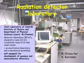
Current Uses of 3He Cryogenics below 1 K, laser research, guided missiles No known alternative Medical imaging of lungs Unique capability Security applications Looking for alternatives Oil well logging Need alternatives Nonproliferation Low probability of finding alternatives Neutron polarization No known alternatives Neutron scattering detectors Need alternatives for large area coverage Ron Cooper 29 September, 2009
Gas Detectors ~25,000 ions and electrons (~4x10-15 coulomb) produced per neutron • 1 part in 104 of natural helium • Obtained from Tritium decay • 3T → 3He + e- + antineutrino • Half-life is 12.3 years • Tritium is produced in reactors mainly for nuclear weapons • The Watts-Bar reactor, near Oak Ridge - scheduled for tritium production - delayed • Accelerator option, 40 3MeV accelerators with 1A beam current each, -20k liters/year 120MW of beam power! 29
Alternative Thermal Neutron Converters 6Li(n,α) reaction: n + 6Li → 3H + 4He Q-value=4.78 MeV E3H=2.73 MeV E4He=2.05 MeV Cross Section → 940 b 6LiF coatings - Chemical Stability Ranges: 3H-32.1 microns; 4He-6.11 microns nabs-174 microns 10B(n,α) reaction: n + 10B → 4He + 7Li [ground state] Q-value=2.792 MeV n + 10B → 4He + 7Li [excited state] Q-value=2.310 MeV ELi =0.84 MeV E4He =1.47 MeV Cross Section → 3836 b 10B coatings Ranges: 7Li-1.6 microns; 4He-3.6 microns nabs -19.9 microns Boron straws 10BF3 (gas) Other reactions: 157Gd(n,γ) (Natural Gd, cross section 49,000 b) 113Cd(n,γ) Less useful gamma-rays and conversion electrons The challenge is to balance thermal neutron conversion efficiency and charged particle transport (while minimizing and/or rejecting gamma-ray response) Range calculations: McGregor, D. S., et al., NIM A 500 (2003) 272-308
Prototype 6Li-lined gas detector that incorporates a Li-coated Mo cathode, a 0.001” stainless steel anode wire, and a Xe fill gas at one atmosphere.
Typical preamplifier output pulse from a neutron interaction. Note the large amplitude of the pulse, which after subsequent amplification in a spectroscopy amplifier, leads to a count in the neutron “peak” (>channel number 1000) shown in the pulse height spectra.
DETAILS OF THE NEUTRON RESPONSE PORTION OF THE PULSE HEIGHT SPECTRA ARE SHOWN FOR THE 6Li-LINED PROPORTIONAL COUNTER USING AN AmLi MODERATED NEUTRON SOURCE -- UNSHIELDED SOURCE (BLACK), A 2” THICK Pb-SHIELDED SOURCE (BLUE), AND FOR A Cd-SHIELDED SOURCE (RED).