Download
1 / 15
150 likes | 278 Views
Learn about the design and implementation of CC-Link IO Blocks including hardware development, software integration, and testing procedures. Follow the journey from concept to production launch and certification.

E N D
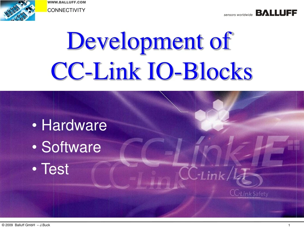
Development of CC-Link IO-Blocks • Hardware • Software • Test
What are we talking about? • One piece zinc die cast housing • fully potted • IP67
Requirements • Productfamily CC-Link IO-Block 16 digital Inputs 8 digital Outputs 8 digital Inputs + 8 digital Outputs 16 free configurable digital Ports • Display for setting and indicating station number and baud rate • CC-Link Ver. 1.10 communication interface • CC-Link certification already available
Development of Hardware
Finding the right Interface Controller Based on existing IO-Block (e.g. Profibus), the protocol ASIC has to be replaced by a Mitsubishi ASIC Decision chart from Mitsubishi MFP3N
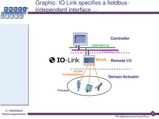
CC-Link Communication hardware Block Diagram Digital IOs Display MPU ASIC MFP3N Communication Interface new hardware parts
Schematic for Implementation Detailed description in the reference manual e.g. isolated communication system circuit Sourcing the specified parts (filter, zener diode) in Europe was not so easy Help from Mitsubishi/CLPA MFP3N
Development of Software
CC-Link Communication Software MFP3N Reference Manual contains • Detailed register description • Detailed flowchart Easy implementation of code, only minor supportfrom Mitsubishi was necesarry
CC-Link Conformance Tests Pre-Tests have to be done by manufacturer All tests are simple to apply, exept one: The noise test • The necessary equipment (noise simulator, isolation transformer) is not known in Europe and difficult to source. • CLPA offers that the tests can be done in Japan First tests were made in Japan • Meanwhile CLPA in Europe ordered the equipment for their lab. Following tests were made in Ratingen • After the tests are passed these modules are directly sent to CLPA in Japan and they made the CC-Link conformace test.
Project finished in August 2009 • Development finished • Release available • EMC tests done • Shock/vibration done • CLPA certification for all 4 products done • Production startup done • First products in stock • Product launch in fall 2009
CC-Link Development Conclusion The reference manual covers nearly all questions. All other questions are answered by Mitsubishi/CLPA Expeditures Hardware development 35% project time Software development 25% project time Tests (Pretest and conformance test) 40% project time