Download
1 / 24
240 likes | 264 Views
Gain insights into propositional calculus concepts and techniques to codify logical statements, reason logically, and understand Boolean functions, rules of Boolean Algebra, logic minimization, and circuit design. Learn to simplify conditional statements using Boolean expressions. Explore the limitations and applications of propositional calculus.

E N D
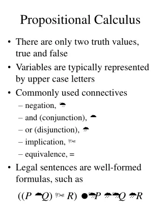
Propositional Calculus • Objective: To provide students with the concepts and techniques from propositional calculus so that they can use it to codify logical statements and to reason about these statements. To illustrate how a computer can be used to carry out formal proofs and to provide a framework for logical deduction. • Topics • Boolean functions and expressions • Rules of Boolean Algebra • Logic Minimization • Tautologies and automatic verification of tautologies • Application to Circuit Design Systems Architecture I
Programming Example • Boolean expressions arise in conditional statements. It is possible to abstract the relations with boolean variables (propositions that are either true or false). Using this abstraction one can reason and simplify conditional statements. • if ((a < b) || ((a >= b) && (c == d)) then { … } else { … } • Let p denote the relation (a<b) and q denote the relation (c == d). The above expression is then equal to • p || !p && q Systems Architecture I
Programming Example (cont) • The previous expression is equivalent (two expressions are equivalent if they are true for the same values of the variables occurring in the expressions) to a simpler expression • (p || !p && q) p || q • We can see this since if p is true both expressions are true, and if p is false, then !p is true and (!p && q) is true exactly when q is true. Systems Architecture I
Limitations of Propositional Calculus • Propositions hide the information in the predicates they abstract. • Sometimes properties of the hidden information is required to make further deductions. • E.G. for integers a,b, and c, (a < b) && (b < c) implies that a < c; however, this can not be deduced without using the order properties of the integers. • The predicate calculus allows the use of predicates to encode this additional information. • E.G. we can introduce a parameterized predicate lt(a,b) to encode the predicate a < b. Properties such as lt(a,b) && lt(b,c) lt(a,c) can be asserted. This type of notation and deduction is discussed in chapter 14. Systems Architecture I
x0 f x1 s Boolean Functions • A Boolean variable has two possible values (true/false) (1/0). • A Boolean function has a number of Boolean input variables and has a Boolean valued output. • A Boolean function can be described using a truth table. • There are 22n Boolean function of n variables. s x0 x1 f 0 0 0 0 0 0 1 0 0 1 0 1 0 1 1 1 1 0 0 0 1 0 1 1 1 1 0 0 1 1 1 1 Multiplexor function Systems Architecture I
Boolean Expressions • An expression built up from variables, and, or, and not. x y x y 0 0 0 0 1 0 1 0 0 1 1 1 x y x + y 0 0 0 0 1 1 1 0 1 1 1 1 x x 0 1 1 0 and or not Systems Architecture I
Boolean Expressions • A Boolean expression is a Boolean function. • Any Boolean function can be written as a Boolean expression • Disjunctive normal form (sums of products) • For each row in the truth table where the output is true, write a product such that the corresponding input is the only input combination that is true • Not unique • E.G. (multiplexor function) s x0 x1 + s x0 x1 + s x0 x1 + s x0 x1 s x0 x1 f 0 0 0 0 0 0 1 0 0 1 0 1 0 1 1 1 1 0 0 0 1 0 1 1 1 1 0 0 1 1 1 1 Systems Architecture I
Boolean Logic • Boolean expressions can be simplified using rules of Boolean logic • Identity law: A + 0 = A and A 1 = A. • Zero and One laws: A + 1 = 1 and A 0 = 0. • Inverse laws: A + A = 1 and A A = 0. • Commutative laws: A + B = B + A and A B = B A. • Associative laws: A + (B + C) = (A + B) + C and A (B C) = (A B) C. • Distributive laws: A (B + C) = (A B) + (A C) and A + (B C) = (A + B) (A + C) • DeMorgan’s laws: A + B = A B and A B = A + B • The reason for simplifying is to obtain shorter expressions, which we will see leads to simpler logic circuits. Systems Architecture I
Simplification of Boolean Expressions • Simplifying multiplexor expression using Boolean algebra s x0 x1 + s x0 x1 + s x0 x1 + s x0 x1 = s x0 x1 + s x0 x1 + s x1 x0 + s x1 x0 (commutative law) = s x0 (x1 + x1)+ s x1 (x0 + x0)(distributive law) = s x0 1+ s x1 1 (inverse law) = s x0+ s x1 (identity law) • Verify that the boolean function corresponding to this expression as the same truth table as the original function. Systems Architecture I
Additional Notation • Several additional Boolean functions of two variables have special meaning and are given special notation. By our previous results we know that all boolean functions can be expressed with not, and, and or; so the additional notation is simply a convenience. x y x y 0 0 1 0 1 0 1 0 0 1 1 1 x y x y 0 0 1 0 1 1 1 0 0 1 1 1 equivalence implication Systems Architecture I
Tautologies • A tautology is a boolean expression that is always true, independent of the values of the variables occurring in the expression. The properties of Boolean Algebra are examples of tautologies. • Tautologies can be verified using truth tables. The truth table below shows that x y x + y x y x y x + y 0 0 1 1 0 1 1 1 1 0 0 0 1 1 1 1 Systems Architecture I
Exercise • Derive the tautology x y x + x from the sum of products expression obtained from the truth table for x y. You will need to use properties of Boolean algebra to simplify the sum of products expression to obtain the desired equivalence. Systems Architecture I
Tautology Checker • A program can be written to check to see if a Boolean expression is a tautology. • Simply generate all possible truth assignments for the variables occurring in the expression and evaluate the expression with its variables set to each of these assignments. If the evaluated expressions are always true, then the given Boolean expression is a tautology. • A similar program can be written to check if any two Boolean expressions E1 and E2 are equivalent, i.e. if E1 E2. Such a program has been provided. Systems Architecture I
Karnaugh Map • A Karnaugh map is a two dimensional version of a truth table. It can be used to simplify Boolean expressions expressed as sums of products. • The example below shows the Karnaugh table for the truth table defining implication. There is a 1 in each box corresponding to each value of p and q where x y is true and a 0 where it is false. Systems Architecture I
Logic Minimization • We want a sum of products that is true for all of the boxes with 1’s (a cover). One such cover is obtained using a product for each individual box. A simpler expression can be obtained using the literals !x and y which cover the first row and the second column respectively. • This shows that x y x + x • This can be generalized to more the one variable (Sec. 12.5) Systems Architecture I
Logic Circuits • A single line labeled x is a logic circuit. One end is the input and the other is the output. If A and B are logic circuits so are: • and gate • or gate • inverter (not) A B A B A Systems Architecture I
x0 x1 s Logic Circuits • Given a boolean expression it is easy to write down the corresponding logic circuit • Here is the circuit for the original multiplexor expression Systems Architecture I
Logic Circuits • Here is the circuit for the simplified multiplexor expression x0 x1 s Systems Architecture I
Nand Gates • A nand gate is an inverted and gate • All boolean functions can be implemented usingnandgates(andand not can be implemented using nand) x y x | y 0 0 1 0 1 1 1 0 1 1 1 0 nand x = x x Systems Architecture I
Decoder • A decoder is a logic circuit that has n inputs (think of this as a binary number) and 2n outputs. The output corresponding to the binary input is set to 1 and all other outputs are set to 0. d0 b0 d1 b1 d2 d3 Systems Architecture I
Encoder • An encoder is the opposite of a decoder. It is a logic circuit that has 2n inputs and n outputs. The output equal to the input line (in binary) that is set to 1 is set to 1. d0 d1 b0 d2 b1 d3 Systems Architecture I
Multiplexor • A multiplexor is a switch which routes n inputs to one output. The input is selected using a decoder. d0 d1 d2 d3 s1 s0 Systems Architecture I
Exercise • Derive a truth table for the output bits (Sum and CarryOut) of a full adder. • Using the truth table derive a sum of products expression for Sum and CarryOut. Draw a circuit for these expressions. • Using properties of Boolean algebra and Karnaugh Maps to simplify your expressions. Draw the simplified circuites. Systems Architecture I
CarryIn a Sum b Full Adder • Sum = parity(a,b,CarryIn) • a xor b xor c + abc a xor b xor c • CarryOut = majority(a,b,CarryIn) • bCarryIn + aCarryIn + ab + abCarryIn • bCarryIn + aCarryIn + ab Systems Architecture I