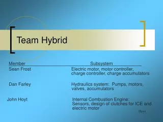
Team Hybrid
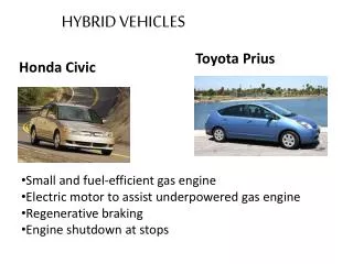
Team Hybrid. Daniel Farley John Hoyt Sean Frost. Hoyt. Background Information. A hybrid vehicle (HV) is a vehicle using an on-board rechargeable energy storage system and a fuelled power source for vehicle propulsion .

Team Hybrid
E N D
Presentation Transcript
Team Hybrid Daniel Farley John Hoyt Sean Frost Hoyt
Background Information A hybrid vehicle (HV) is a vehicle using an on-board rechargeable energy storage system and a fuelled power source for vehicle propulsion . The HV pollutes less and uses less fuel. The different propulsion power systems may have common subsystems or components. The HV provides better fuel economy than a conventional vehicle because the engine is smaller and may be run at speeds providing more efficiency. Hoyt
Problem Statement: Vermont Technical College would like to compete in the Dartmouth Thayer School of Engineering Formula One Hybrid Racing Competition, but we do not currently have a vehicle that meets the specifications. Farley
Solution Statement: To develop and construct a Hybrid propulsion system which comprises both an internal combustion engine (ICE) and an electrical storage unit and electric drive, which shall meet all electrical specifications and requirements for the 2007 Dartmouth Thayer School of Engineering Formula One Racing Competition. The Drive system may deploy the ICE and electric motor(s) in any configuration including series and parallel. This drive train system can then be adapted to a chassis developed in a separate effort. Farley
Hybrid Propulsion System Overview System Overview ICE Power Split Device 4 port, 3 way valve V+ Hydraulic Pumps Hydraulic Motors Generator Accumulator Axle Assembly V+ Electric Motor Check valves Battery Bank LowPressure Feedback Frost
Internal Combustion and Clutch/Pump Subsystem (Hydraulic Drive Sub-System) Electric Clutch ICE Hydraulic Pump Belt connection To the ICE V+ Electric Clutch Generator FB1-4001A #1 Clutch Control Signal Hydraulic Pump Hoyt FB1-4001A #2
Electrical Motor/Generator & Controllers Subsystem (Control Sub-System) Manzanita Micro PFC-20 charge controller Belt connection To the ICE Electrical charge accumulator Generator V+ Frost Raptor 1200 Motor Controller Hydraulic Pump +120 VDC Electric Motor FB1-4001A Frost
Accumulator 2 Hydraulic Subsystem Overview (Hydraulic Driven Sub-System) 4 Port, 2 Way Electronically Controlled Valve Check Valve ICE Input Accumulator 1 Reservoir Electric Motor Input Hydraulic Motor Electronically Controlled Flow Valve Hydraulic Pump 4 Port, 2 Way Electronically Controlled Valve
Delete this Slide Power Splitting Device A parallel drive train allows both the ICE and electric motor to operate simultaneously or independently. Most parallel system incorporate a complex mechanical power splitting device; commonly a planetary gear set. Farley
ICE Power Split Device V+ Hydraulic Pumps Generator Hydraulic Motors High Pressure Axle Assembly V+ Electric Motor Battery Bank Farley LowPressure Hydraulic System Used as Power Splitting Device • The rotational input from both the electric motor and ICE will drive hydraulic pumps • to pressurize the accumulator. The hydraulic pressure will act on hydraulic motors • positioned at the drive wheels to power the vehicle. • Regenerative braking will allow the hydraulic motors to pressurize fluid back into the • accumulator for future use.
Full Acceleration State Diagram Full Accel. Tire ICE OFF Standby Efficiency Elec. motor Accumulator Reg. Drive Efficiency Tire ICE Regular Drive Elec. motor Accumulator Tire ICE Elec. motor Accumulator Modes of Operation
Personnel Assignments -Mathematical Modeling of the system (ICE, electric motor, hydraulics) Sean Frost -Test ICE motor with generator for feasibility John Hoyt -Rate the hydraulic motors and pumps needed through calculations. Dan Farley -Pricing, ordering Hydraulic parts (motors, pumps, valves, etc.)Dan Farley -Make a decision whether to use hydraulics or not (monetary & avail. restraints) John Hoyt Dan Farley Sean Frost -Address compatibility issues with electric motor and controller. John Hoyt Sean Frost -Address interfacing between ICE, generator, & electric motor. Sean Frost John Hoyt Frost
Delete this Slide Speed Sensing Research into the Hall Effect has proven that Hall Effect speed sensors may need to be implemented in the system. Uses Traction control feedback from wheels Output speed feedback from ICE and electric motor Advantages Readily available No physical connection required (efficiency) Nature elements not an issue Hoyt
Summary • In order to compete in the Thayer School of Engineering Formula One Hybrid Competition, a hybrid drive-train is essential. • Team Hybrid will design and construct a hybrid propulsion system that meets the required specifications. • Several technical topics must be considered when designing this type of system. These topics still need to be further researched. Hoyt