
Uploaded by
parley
8 SLIDES
198 VIEWS
80LIKES
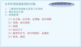
由零件图画装配图的步骤:
DESCRIPTION
画球阀装配图示例. 由零件图画装配图的步骤:. 1 、了解部件的装配关系和工作原理 2 、确定表达方案 3 、画装配图. ( 1 )定方案,定比例,定图幅,画出图框 ( 2 )布图,画出基准 ( 3 )画图 ( 4 )标注尺寸 ( 5 )编零件序号、填写明细栏、标题栏 ( 6 )检查、描深. 球阀画图 1. 1. 确定图幅. 图幅要根据视图表达方案,部件的大小与复杂程度以及采用的比例来确定。 要注意安排各视图的位置,并留有标注零部件序号、明细栏、以及注写尺寸及技术要求的空间。. 2. 画底稿. (1) 画主轴线.
Download
1 / 8
Download Presentation 
由零件图画装配图的步骤:
An Image/Link below is provided (as is) to download presentation
Download Policy: Content on the Website is provided to you AS IS for your information and personal use and may not be sold / licensed / shared on other websites without getting consent from its author.
Content is provided to you AS IS for your information and personal use only.
Download presentation by click this link.
While downloading, if for some reason you are not able to download a presentation, the publisher may have deleted the file from their server.
During download, if you can't get a presentation, the file might be deleted by the publisher.
E N D
Presentation Transcript
画球阀装配图示例 由零件图画装配图的步骤: 1、了解部件的装配关系和工作原理 2、确定表达方案 3、画装配图 (1)定方案,定比例,定图幅,画出图框 (2)布图,画出基准 (3)画图 (4)标注尺寸 (5)编零件序号、填写明细栏、标题栏 (6)检查、描深
球阀画图1 1.确定图幅 图幅要根据视图表达方案,部件的大小与复杂程度以及采用的比例来确定。 要注意安排各视图的位置,并留有标注零部件序号、明细栏、以及注写尺寸及技术要求的空间。 2.画底稿 (1) 画主轴线
球阀画图2 (2) 画轴线上主要零件(阀体)的轮廓线。
球阀画图3 (3) 根据相对位置,沿水平轴线画出阀盖的轮廓线。
球阀画图4 (4) 根据相对位置,沿水平轴线画出法兰及螺柱连接的轮廓线。
球阀画图5 (5) 根据相对位置,沿竖直轴线画出其余各个零件的轮廓线。
球阀画图6 (6) 检查整理,画剖面线。
球阀画图7 3. 底稿完成后,加粗加深,标注必要的尺寸,编写零件序号,填写明细栏和标题栏。
More Related