Download
1 / 17
170 likes | 174 Views
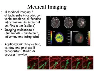
Learn how to set up and operate the Olympus FV1000 Confocal Microscope at Harvard Medical School's Neurobiology Imaging Facility. Follow step-by-step instructions for finding an area of interest, adjusting settings, acquiring single plane and multiple Z-plane images, and more.

E N D
Olympus FV1000 Confocal Microscope Harvard Medical School Neurobiology Imaging Facility (NIF) Michelle OcanaDirectormichelle_ocana@hms.harvard.edu617-275-6390
UCB Hg Illuminator Halogen light Source Air Table & Scope Monitor #1 Hg Power Power strip #2 Key always on Key always on PC #3 PC Laser Combiner Your Set up and Turn On Order • Turn on PC if not already on • Turn on Hg power supply under air table • Turn on Power strip • Turn 488nm laser power key • Turn the 559 laser key
Your Hand Keypad Halogen Lamp Shutter Hg Lamp Shutter Transmitted/Fluorescence toggle TSHT RSHT DIC CY5 TRITC DAPI FITC Objectives
Windows XP Login: Neurobiology Password: none Fluoview Software (FV-ASW) Login & Password to be assigned at training Do not allow untrained lab members to use your login. They must be training by the facility. You and your lab may be suspended from using the scope!
Finding an area of interest 1. Mount slide or dish on microscope stage 2. Find an area of interest using the microscope oculars and the appropriate light source (bright-field or fluorescence) a. Upon selecting the Bright Field or Fluorescent light button, the light path should automatically be set to the oculars Brightfield Epi
Choose the correct filter cube for your sample (on the key pad or in microscope control box): DIC for Brightfield Light DAPI – Blue Fluorescent light FITC – Green Fluorescent Light TRITC – Red Fluorescent Light CY5 – Far Red Fluorescent Light Choose the appropriate objective for your sample (on key pad or in microscope control box): 10x 0.40 NA AIR 20x 0.75 NA AIR 40x 1.3 NAOIL 60x 1.42 NA OIL 100x 1.45 NA OIL Water and Silicone lenses are available. Please ask for them if needed. The filter wheel setting will automatically go to position 1 for Laser Scanning (LSM) when prompted by the software The DIC prism will automatically switch to the appropriate position for DIC imaging. You must place the polarizer into the light path.
Access the dye list from the Image Acquisition control panel 1. Select the appropriate dyes for your sample from the Dye List 2. Click Apply 3. Selected Dye(s) configuration will then be loaded into the Image Acquisition Control Window Select Dye Double Click to add selected dye. Maximum of four dyes
**Optional**: Checking the Spectral Settings 1. Click VBF 2. Make sure dyes are well separated with no overlap in signal by adjusting the emission filters for each channel 3. Before you begin scanning with the lasers, check your Acquisition settings
Always have AutoHv activated Objective Change Setting the Z Position Sets the Optimal Z step for your sample Time Series
Image Acquisition • Start laser scanning by clicking the XY Repeat button, Focus x2, or Focus x4 2. Select Ctrl H on the keyboard to view image in intensity mode for adjustments 3. Select Sequential check box if using more than one dye. 4. Adjust the HV so the signal is not saturated, indicated by RED pixels 5. Adjust the Offset so the background contains no blue pixels 6. Repeat for all channels 7. To stop the live scan, click the Stop button
Acquire a Single Plane Image • Select all channels you wish to scan and set up using previous imaging instruction. • Choose Sequential check box at the bottom of the Image Acquisition Control Window if using more than one dye • Click on the TD channel check box to activate transmitted image (brightfield) • Choose appropriate pixel size (resolution) in the Acquisition Settings Window • Select Focus x2 • Use CNTRL + H to view image in intensity range mode • Adjust Hv for brightness and Offset for background for each channel. • Select the XY button to acquire the image • Save the image by right clicking on the image window and choosing Save from the drop menu. Use .oib format
Acquire a Multiple Z-Plane • Select all channels you wish to scan and set up using previous imaging instruction. • Adjust Scan Speed on the Acquisition Setting window making sure Auto HV is selected. • Click the Depth button on the Image Acquisition Control window • Choose Fast XY, click on the up arrow and down arrow in Microscope control area of Image Acquisition Settings window. • Click on the Set button to save position for both top and bottom of sample. • Save the image by right-clicking on the image window and selecting Save As. Designate location and image name. • Save as .oib (single Olympus file with Header, Image, and property files) or ,oif (Multiple files and .tiffs with separate Header file)
Acquire a Multiple Z-Plane 1. Follow directions for setting up a single plane scan or Z-series depending on your needs 2. In the Time Scan section of the Acquisition Settings window set the interval between scans, and the total number of scans needed. 3. On the Image Acquisition Control Window, select TIME under the XY button 4. If you wish to do a Z-series as well as a time series, select the DEPTH button under the XY button as well, changing the button to XY ZT
Acquire a Lambda Stack • Select CH1. Remove current dye by dragging out of the field. • Turn on appropriate lasers. • Select lamda in Image Acquisition Control window • Choose the Range for the Lambda Scan either by changing the nm setting in the Lambda Scan section of the Acquisition Setting Window or by selecting Spectral View • Choose a step size • Use Focusx2 to adjust Hv, offset and laser power checking all positions to eliminate saturated pixels. Using Spectral View window to step through wavelengths. • Press XY L button to acquire image. Engage the Lambda button on the Image Acquisition Control Window and run the XY lambda scan
Deconvolving Your Image • When scan is finished, Select Series Done to conclude or Append Next to add more scans • To process the Lambda scan and separate signals, Go to PROCESSING and select SPECTRAL DECONVOLUTION • The Spectral Profile Deconvolution window will appear. • Click on the Calculate box to assign a random value to as many dyes as you would like to separate. In the example, two dyes are being separated. A color may be applied to each line on the graph by clicking the COLOR section of the Random Value and assigning a specific color (shown in Red and Green). • Select ROIs on the lambda scan to indicate the different wavelengths found. • Choose NORMAL Processing type for known dyes and ROI’s, and BLIND for unknown signals. • Once you assign these random values, click NEW IMAGE to separate the dyes. An Auto Result Dye for each random value will be generated, as shown in the example. • These dyes can be saved into your dye list by selecting SAVE PROFILE and providing a name.
Turning off the System: Only shut down the system if you are the last person of the day or if there is more than 3 hours between you and the next user. • Close the Olympus Fluoview software • Turn off the power strip • Turn the 488 and 559 laser power keys off • Turn off Hg power supply