Download
1 / 33
530 likes | 1.44k Views
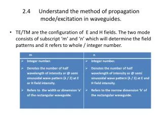
2.4 Understand the method of propagation mode/excitation in waveguides. TE/TM are the configuration of E and H fields. The two mode consists of subscript ‘m’ and ‘n’ which will determine the field patterns and it refers to whole / integer number.

E N D
2.4 Understand the method of propagation mode/excitation in waveguides. • TE/TM are the configuration of E and H fields. The two mode consists of subscript ‘m’ and ‘n’ which will determine the field patterns and it refers to whole / integer number.
The propagation mode of TE and TM in the rectangular waveguide depends on critical / cutoff method used. • The characteristics used to identify the critical / cutoff method are fc (f0) and λc ( λ 0). • Different TE and TM modes all have different cutoff wavelength and therefore encounter different characteristic wave impedance. Eg. TM11, TM12 etc. • The dimension of the waveguide and the propagation modes used is affected by the cutoff wavelength / frequency (f0 and λ 0). • Only certain frequency / wavelength are being allowed to propagate in the waveguide.
ModeTE m,n • The TE, or transverse electric, mode have electric fields in the transverse plane, that is, only across the waveguide. • The magnetic field in the TE mode runs both transversely and axially along the waveguide. • The electric field are transverse and the magnetic field are extend across the cross section and along the waveguide itself. • The subscript after the TE or TM refers to the number of electric or magnetic field variation across the height and width of the waveguide. • For example, in the TE0,1 mode, the electric field is uniform with no variations across the height dimension, but has one variation across the width. The field goes from zero at edge of the guide to a maximum at the center and back to zero at the opposite end of the guide. • For TE0,2mode, the electric field still has no variations across the height of the guide, but has two variations across its width. The field goes from zero at the one edge of the guide, to a maximum, to zero, to a maximum with the opposite field direction, and then back to zero at the other guide wall.
ModeTEm,n • Refers to the existence of one half wavelength (λ / 2) across the guide width (m) and narrow dimension (n). • Needs modification of wave. They are used in practice as often as the TEmo mode (except TE11 mode which does have some practical application. • Eg. TE 11 (1,1 – has one λ / 2 at guide width and narrow dimension ). λ / 2 λ / 2
Mode TM m,n • The TM or transverse magnetic mode , have magnetic fields that exist only in the transverse and axial direction along the guide. • H field across the propagation direction • Loop can be seen at front view. • Loop cannot be seen on top view. • 1 loop = half wavelength, λ / 2.
TM 11 –half wavelength (λ / 2) exist at guide width & half of E field intensity exist at narrow dimension. • Side view – E field ends at 90°. • TM modes are govern by relations identical to those governing TEmn modes except that the equation for characteristic wave impedance Z0.
2.4.2 Explain how to excite the dominant modes for propagation mode in TE m,n and TM m,n
The cut off frequency can be shown graphically below Single mode 3 modes 4 modes TE 11 Dominant mode TE00 TE 20, TE 01 TE 10 f Figure : Composite table of fcfor different TE mode.
The analysis can be carried out for TM modes, yielding results which are similar to those obtained previously with TE mode . • Excersice : The WG-16 waveguide recommended for X-band (8-12GHz) transmission has dimension a=0.9” and b=0.4”. Calculate the frequency range over which the dominant mode propagates.
Waveguide Components Waveguide components are: a. Connectors/Joint b. Attenuators c. Coupler d. Basic accessories (bends, corner, tapered, twist) e. Junction-T and Hybrid-T
Attenuators • Attenuator works by putting carbon vane or flap into the waveguide • Currents induced in the carbon cause loss • Load is similar but at end of guide
Coupler • Launches or receives power in only 1 direction • Used to split some of power into a second guide • Can use probes or holes
BASIC ACCESSORIES (Bends, corner, tapered, twist) • Bends • Called E-plane or H-Plane bends depending on the direction of bending
Tees • Also have E and H-plane varieties • Hybrid or magic tee combines both and can be used for isolation
Junction-T • Waveguide junctions are used when power in a waveguide needs to be split or some extracted. • There are a number of different types of waveguide junction that can be use, each type having different properties - the different types of waveguide junction affect the energy contained within the waveguide in different ways.
Waveguide junction types • There are a number of different types of waveguide junction. The major types are listed below: • H-type T Junction: This type of waveguide junction gains its name because top of the "T" in the T junction is parallel to the plane of the magnetic field, H lines in the waveguide. • E-Type T Junction: This form of waveguide junction gains its name as an E- type T junction because the tope of the "T" extends from the main waveguide in the same plane as the electric field in the waveguide. • Magic T waveguide junction: The magic T waveguide junction is effectively a combination of the E-type and H-type waveguide junctions. • Hybrid Ring Waveguide Junction: This form of waveguide junction is another form of waveguide junction that is more complicated than either the basic E-type or H-type waveguide junction.
E-type waveguide junction • It is called an E-type T junction because the junction arm, i.e. the top of the "T" extends from the main waveguide in the same direction as the E field. It is characterized by the fact that the outputs of this form of waveguide junction are 180° out of phase with each other.
H-type waveguide junction • This type of waveguide junction is called an H-type T junction because the long axis of the main top of the "T" arm is parallel to the plane of the magnetic lines of force in the waveguide. It is characterized by the fact that the two outputs from the top of the "T" section in the waveguide are in phase with each other.
Magic T Hybrid • It is a combination of the H-type and E-type T junctions. The most common application of this type of junction is as the mixer section for microwave radar receivers.
When a signal is applied into the "E plane" arm, it will divide into two out of phase components as it passes into the leg consisting of the "a" and "b" arms. However no signal will enter the "E plane" arm as a result of the fact that a zero potential exists there - this occurs because of the conditions needed to create the signals in the "a" and "b" arms. In this way, when a signal is applied to the H plane arm, no signal appears at the "E plane" arm and the two signals appearing at the "a" and "b" arms are 180° out of phase with each other. • When a signal enters the "a" or "b" arm of the magic t waveguide junction, then a signal appears at the E and H plane ports but not at the other "b" or "a" arm as shown.
Hybrid ring • This form of waveguide junction overcomes the power limitation of the magic-T waveguide junction. • A hybrid ring is constructed from a circular ring of rectangular waveguide - a bit like an annulus. The ports are then joined to the annulus at the required points. Again, if signal enters one port, it does not appear at all the others. • The hybrid ring is used primarily in high-power radar and communications systems where it acts as a duplexer - allowing the same antenna to be used for transmit and receive functions. • During the transmit period, the hybrid ring waveguide junction couples microwave energy from the transmitter to the antenna while blocking energy from the receiver input. Then as the receive cycle starts, the hybrid ring waveguide junction couples energy from the antenna to the receiver. During this period it prevents energy from reaching the transmitter.
2.5.1 Explain the application of waveguide components • Slotted section • Isolator • Circulator • Mixers
Slotted section • A slotted is a transmission line configuration (usually a waveguide or coaxial line)that allows the sampling of the electric field amplitude of a standing wave on a terminated line. • With this device the SWR and the distance of the first voltage minimum from the load can be measured, and from these data the load impedance can be determined.
Circulator and Isolator • Both use the unique properties of ferrites in a magnetic field • Isolator passes signals in one direction, attenuates in the other • Circulator passes input from each port to the next around the circle, not to any other port Circulator Top View PRECESSION
Mixers • The mixer takes two signals and combines them creating new signals. It can be used to translate microwave signals into much lower frequencies that an inexpensive radio receiver can tune. It can even reverse the effect taking low frequencies and translating them back into the microwave range. • Mixers are needed in most microwave systems because the RF signal is way too high to process its information (for example, looking for a Doppler shift in an X-band radar application, you won't find many A/D converters than can handle 10 GHz!)
Mixer ports • There are three ports on a mixer, the radio frequency (RF) port, the local oscillator port (LO), and the intermediate frequency port (IF). • The RF port is where the high frequency signal is applied that you want to down convert it, or where the high-frequency signal is output in an up converter. • The local oscillator (LO) port is where the "power" for the mixer is injected. In this case, the power that is applied is RF, not DC like it would be in an amplifier. The LO signal is the strongest signal, and is used to turn the diodes on and off in a switching mixer (which is nine out of ten mixers). The switching action effectively reverses the path of the RF to the IF. • The IF port is where the RF signal that was modified by the LO signal is passed, and its waveform is filtered to become the IF signal