Download
1 / 57
570 likes | 630 Views
Explore Snell's Law and how it determines the bending of light as it passes through different mediums. Learn about the concept of total internal reflection and its applications in fiber optics and binoculars.

E N D
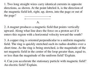
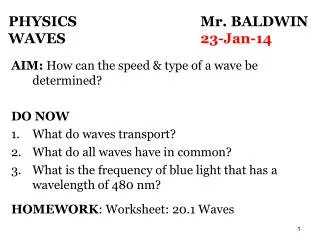
PHYSICS Mr. BALDWINGEOMETRIC OPTICS2-Jan-20 AIM: What does a spoon or pencil look like in a clear glass of water? DO NOW: If an object is located on the reflective side of a mirror, is it’s distance positive or negative? If an image is located on the reflective side of a mirror, is it’s distance positive or negative? If the focal point of a mirror is located on the reflective side of a mirror, is it’s distance positive or negative? BALDWIN 1
Refraction: Snell’s Law Light changes direction (bends) when crossing a boundary from one medium to another. This is called Refraction. The angle the outgoing ray makes with the normal is called the angle of refraction.
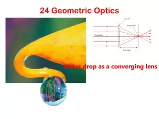
Refraction: Snell’s Law Refraction is what makes objects half-submerged in water look odd. http://interactagram.com/physics/optics/refraction/
Index of Refraction Light slows when traveling through a medium. The index of refraction, n, of the medium is the ratio of the speed of light in vacuum to the speed of light in the medium:
PHYSICS Mr. BALDWINGEOMETRIC OPTICS2-Jan-20 AIM: What is Snell’s Law? (How do we determine how much a light ray bends when it enters a medium?) DO NOW: A ray of light enters into a piece of plexiglas. The refractive index of plexiglas is 1.51. What is the speed of light when it enters the plexiglas? Take the speed of light to be 3.0 x 10⁸ m/s. Homework: Refraction Handout BALDWIN 5
Refraction: Snell’s Law The angle of refraction depends on the indices of refraction, and is given by Snell’s law: Using Snell’s law, what is the refracted angle?
When a ray of light crosses from one material to another, the amount it bends depends on the difference in index of refraction between the two materials. Snell’s Law
PHYSICS Mr. BALDWINGEOMETRIC OPTICS2-Jan-20 AIM: How does light travel in a fiber optic cable? (An application of Snell’s Law) DO NOW: (Quiz) A ray of light enters into a diamond at 30 degrees. The refractive index of diamond is 2.42. What is the speed of light when it enters the diamond and what is the refracted angle? Take the speed of light to be 3.0 x 10⁸ m/s. Homework: None BALDWIN 8
Total Internal Reflection; Fiber Optics If light passes from one medium into another medium with a smaller index of refraction, IS the angle of refraction larger or smaller? LARGER There is an angle of incidence that will make the angle of refraction equals 90°; this angle is called the critical angle. Thus, derive an expression for the critical angle using Snell’s Law.
Total Internal Reflection If the angle of incidence is larger than this (critical angle), no transmission occurs. The light is trapped. This is called total internal reflection. Based on the diagram, which letter represents TIR?
Challenge. • Fused silica has a refractive index of 1.46. Calculate its critical angle. • The critical angle for diamond is 24o. Determine the refractive index of diamond. • Find the subsequent paths of rays of light incident internally on the surface of fused silica at angles of incidence of: (a) 35o (b) 65o
Describe an application of total internal reflection used in the communications industry. Application of Total Internal Reflection: Fiber Optics Total internal reflection is also the principle behind fiber optics. Light will be transmitted along the fiber even if it is not straight. An image can be formed using multiple small fibers.
Total Internal Reflection: Binoculars Binoculars often use total internal reflection; this gives true 100% reflection, which even the best mirror cannot do.
WORKSHEET No.2: 1. Calculate the absolute refractive index for a clear plastic material, if the velocity of light in the plastic is 2.5 x 10⁸ ms-1. (1.2) 2. A ray of light in air is incident at an angle of 40.8o on the surface of the same plastic material used in Q.1. Determine the angle of refraction in the plastic. (33o) 3. A ray of light passes from kerosene to glass. The angle of incidence of the light is 45.2o and the relative refractive index from kerosene to glass is 1.08. Calculate the angle of refraction in the glass. (41o) 4. Using relevant information from Q.3, calculate the absolute index of refraction of kerosene if the absolute index of refraction of glass is 1.5. (1.39) 5. A ray of light passes from air into a glass prism at an angle of incidence of 35o. If the angle of refraction in the glass is 23.7o, what is the speed of the light in the glass? (2.1 x 10⁸ ms-1)
6. The absolute refractive index of water is 4/3 and that of glass is 3/2. Find the relative refractive index for light traveling from water to glass. 7. The critical angle for diamond is 24o. Determine the refractive index of diamond. 8. Fused silica has a refractive index of 1.46. Calculate its critical angle. (43.2o) Find the subsequent paths of rays of light incident internally on the surface of fused silica at angles of incidence of: (a) 35o (b) 65o 9. Describe an application of total internal reflection used in the communications industry. 10. For yellow light, the refractive index of glass is 1.6 and the refractive index of water is 1.2. Which of the following statements is correct? (a) The wavelength of yellow light in glass is longer than the wavelength of yellow light in water. (b) For the same angle of incidence, yellow light is refracted more by water than glass. (c) Total internal reflection cannot occur when yellow light travels from water to glass. (d) Light travels faster in glass than in water.
PHYSICS Mr. BALDWINGEOMETRIC OPTICS2 January 2020 AIM:How are images formed by plane mirrors? DO NOW: How far inside a plane (flat) mirror do you appear to be when you are standing in front of one? How large is your image? Is there anything else about your image you observe? HOME WORK – Handout BALDWIN 16
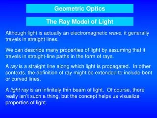
The Ray Model of Light Light very often travels in straight lines. We represent light using rays, which are straight lines emanating from an object.
Recall: What is The Law of Reflection? Q: How are the angles measured again? A: The angles of incidence/reflection are the angles that are measured from the normal to the incident/reflected ray.
Reflection: Image Formation by a Plane Mirror Q: What you see when you look into a plane (flat) mirror? Describe the image (its dimensions, its location)? the image appears to be behind the mirror.
DRAWING A RAY DIAGRAM FOR A PLANE MIRROR • For an object standing in front of a plane mirror, we can locate the image by extending (extrapolating) two of the rays coming from the top of the object and finding their point of intersection. • .
Thus we have found the position of the image, its magnification, and its orientation (whether it is inverted or upright). • What can be said about the characteristic of an image formed by a plane mirror? (Describe the image?) • Object/Image distances? • The distance of the object from the mirror equalsthe distance of the image from the mirror. • Image height? (magnification?) • The image is the same height as the object, so the magnification = 1. • Orientation? • The image is upright.
How can an image lie behind a mirror hanging on a wall, when no light can reach that point? • Does light actually pass through the position where the image is located? • The light never gets behind the mirror at all, it just appears to come from points behind the mirror as it is reflected. • Since the light never actually passes through the point where the image is located, the image is called virtual.
VIRTUAL IMAGES This is called a virtual image, as the light ray does not go through it (image). Note: The distance of the image from the mirror is equal to the distance of the object from the mirror.
DESCRIBING THE PROPERTIES OF AN IMAGE USE SALT! S – Size of image (larger, smaller, same) A – Attitude of image (way image is oriented (inverted, upright?) L – Location of image T – Type of Image (real or virtual)
PHYSICS Mr. BALDWINGEOMETRIC OPTICS2 January 2020 AIM: How do we construct a ray diagram for a spherical mirror? DO NOW: Describe the image formed by the security mirrors in your neighborhood bodegas, elevators, ATMs or in any department stores. What are their purpose? What is S.A.L.T.? HOME WORK – none BALDWIN 27
Spherical Mirrors Spherical mirrors are shaped like sections of a sphere, and may be either reflective on the outside (convex) or reflective on the inside (concave).
Spherical Mirrors Parallel rays striking a spherical concave mirror all converge at exactly the same point called the focal point. The distance from mirror to focus is called the focal length f
Spherical Mirrors Using geometry, we find that the radius of curvature is twice the focal length:
Images formed by Spherical Mirrors We use ray diagrams to determine where an image will be. For mirrors, we use THREE key rays, all of which begin on the TOP of the object: • A ray parallel to the axis; • A ray after reflection it passes through the focal point; • A ray through the radius of curvature
DRAWING A RAY DIAGRAM Mirror Ray 1 Object Ray 2 Ray 3 Image Principal Axis Radius of Curvature Focal Point
Question?...How would do you describe (SALT) the image? • Size – Smaller, larger or equal? • Smaller than object. • Attitude – Erect or Inverted? • Inverted • Location – In front of or behind the mirror? • In front the mirror • Type – Real or Virtual? • Real
Characteristics of Images Formed by Concave (Converging) Mirrors If an object is inside the focal point, its image will be upright, larger, and virtual.
Formation of Images by Spherical Mirrors The Mirror Equation: an equation that relates the object distance, image distance, and focal length of the mirror:
Formation of Images by Spherical Mirrors We can also find the magnification (ratio of image distance/height to object distance/height). Note: The negative sign indicates that the image is inverted.
PHYSICS Mr. BALDWINGEOMETRIC OPTICS10 January 2013 AIM: How do we construct a ray diagram for a Convex Mirror? DO NOW: Draw the ray diagram and describe the characteristics of an image formed by a concave mirror if the object is placed between the radius of curvature & focal point? HOME WORK – Prepare for Test next week Friday BALDWIN 37
Characteristics of Images Formed by Spherical Mirrors If the object is between the center of curvature and the focal point, its image is • Larger, inverted, and real. If an object is outside the center of curvature of a concave mirror, its image is • Smaller,inverted, and real.
Characteristics of Images Formed by Convex (Diverging) Mirrors • For a convex mirror, the image of an object placed anywhere in front the mirror is ALWAYS • Virtual • Upright • Smaller
DRAWING A RAY DIAGRAM Ray 1 Ray 2 Object Ray 3 Principal Axis Radius of Curvature Focal Point Mirror
Review: Characteristics of Images Formed by Spherical Mirrors Sign conventions: if the object distance, image distance, or focal length is on the reflective side of the mirror, its distance is positive, and negative otherwise. Magnification is positive if image is upright, negative otherwise.
PHYSICS Mr. BALDWINGEOMETRIC OPTICSReview What is the distance from the focal point to mirror along the principal axis called? Twice the distance from the focal point to mirror along the principal axis is called? What is another name for a concave mirror? What is another name for a convex mirror? How do we construct a ray diagram? What type of images are formed by a plane mirror? BALDWIN 42
PHYSICS Mr. BALDWINGEOMETRIC OPTICS2 January 2020 AIM: How are images produced by thin lenses? DO NOW: Quick Review What is the distance from the focal point to mirror along the principal axis called? Twice the distance from the focal point to mirror along the principal axis is called? What is another name for a concave mirror? What is another name for a convex mirror? How do we construct a ray diagram? What type of images are formed by a plane mirror? BALDWIN 43
Thin Lenses; Ray Tracing • Thin lenses are made of transparent materials whose thickness is small compared to their radius of curvature. • They may be either • converging • diverging.
CONVEX LENS Parallel rays are brought to a focus by a CONVEX (converging) lens (one that is thicker in the center than it is at the edges).
CONCAVE LENS A CONCAVE (diverging) lens (thicker at the edges than in the center) make parallel rays of light diverge; the focal point is that point where the diverging rays would converge if extrapolated.
Thin Lenses; Ray Tracing • Ray tracing for thin lenses is similar to that for • mirrors. We have three key rays: • One ray travels parallel to the principal axis • A second ray passes through the focal point. • A third ray goes through the center of the lens and is undeflected.
CONVEX LENS For a CONVERCING LENS, we can use three rays; the IMAGE characteristics (real, virtual, upright, inverted, larger, smaller) are determined by the OBJECT’S location.
How would you describe the previous image? • S.A.L.T. • IMAGE is real, inverted, smaller and on the opposite side of the lens.
DRAWING A RAY DIAGRAM Ray 1 Ray 3 Object Ray 2 Principal Axis Focal Point Image Focal Point Concave Lens