
Enhancing Copper Electroplating for Chip Interconnect Structures
Explore the impact of electrolyte additives on copper electroplating for chip interconnect structures, including pattern density effects and additive influence on deposition characteristics. The study investigates electrodeposition parameters, defects, and the role of accelerators, suppressors, and levelers. Analyzing the current-voltage profiles of different electrolytes and wafer patterns, the research delves into the nucleation process and surface morphology changes during copper electrodeposition. Discover the cathodic potential shifts with additives and their inhibition effects on copper deposition. Understand defect causes and optimal current ranges for secure plating.

Enhancing Copper Electroplating for Chip Interconnect Structures
E N D
Presentation Transcript
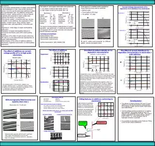
M1 V1 • Introduction. • The successful implementation of copper electroplating in the metallization of chip interconnect structures derives from the use the electrolyte additives to affect the local deposition rate. The additives compounds added in copper plating solution to improve deposit properties are consumed on wafer surface and suppress the kinetics of Cu deposition. • Since interior location of trenches and vias are less accessible to any additives, less suppression of the reaction kinetics occurs there, causing higher deposition rates and supperfilling of trenches and vias . • Objectives of initial stage of copper electroplating study were: • Evaluation of copper electroplating features in commercial electrolytes used within electroplating process • Estimation of the effect of wafer density patterning (M1 and V1) on the electrochemical characteristics of copper electrodeposition. • Determination of the effect of additives additions (accelerator, suppressor and leveler) on electroplating parameters Two types of acid copper electrolytes were examined: 1- low copper content & high acidity (pH 0.7) 2- high copper content & low acidity (pH 1.9) Three types of Cu seeded wafers supplied by Tower/Motorolla were used as substrate: • Blanket wafer • Trench pattern (M1 step) • Via pattern (V1 step) Current-Voltage characteristic of Cu deposition from additives free electrolytes Electrolyte 2 Copper40 g/L Sulfuric acid 10 g/L Chloride 50 ppm Accelerator 2.3 ml/L Suppressor 8 ml/L Leveler 1.5 ml/L Electrolyte 1 Copper 17 g/L Sulfuric acid 180 g/L Chloride 50 ppm Accelerator 2.3 ml/L Suppressor 8 ml/L Leveler 1.5 ml/L Electrolyte 1 The study of electrochemical characteristics of copper deposition was performed in 3-electrode electrochemical cell equipped with Pt counter electrode and saturated calomel reference electrode: Electrolyte 2 Techniques & Methods: Electrochemical Tests: Potentiostatic measurements; Galvanostatic measurements. Surface Examination: SEM, HRSEM, EDS M1 and V1 wafers were presented by different pattern density and aspect ration. The effect of additives on current-voltage profile of Cu in high acidic electrolyte. The effect of additives The effect of pattern density on Cu deposition characteristics The effect of current density on Cu deposition characteristics in electrolyte 1 with additives Electrolyte 2 &Blanket Suppressor Electrolyte 1 without additives Blanket wafer M1 Leveler Voltage/time curves in galvanostatic mode are shown the small shift in potential in the first few second of Cu electrodeposition onto blanket and patterned wafers from additives free electrolyte. These potential changes likely relate to initial nucleation and surface morphology changes. Voltage/time curves are presented more polarized values of voltages at initiation of Cu deposition for M1 and V1 patterned wafers in electrolyte with additives than in electrolyte without additives. This increase in cathodic potential is provided by suppression of Cu deposition by additives. After several seconds the cathodic potential is decreased and depolarization effect occurred over a longer period of time . This effect is increased with metal lines density and disappeared with increasing of current density. V1 Accelerator The combined action of the all three additives are provided inhibition of the Cu deposition reaction relative to additive free electrolyte, although an acceleration of the Cu deposition relative to the suppressor and suppressor&leveler additives electrolytes. Detectable Defects: Filling features in additives containing Cu electrolytes Conclusions: SEM micrographs filled trenches and squares (face view ) • Swirl defects Single pit • Pits clusters Missing via • Embedded defects Localized protrusion defects (LPDs) Main electrochemical causes of defects : • Poor wetting of seed layer at the electroplating start • Particles trapped in trenches and vias (sludge) • Sporadic, localized growth due to organic additives Large molecules of suppressor adsorbs preferentially on the outside of trenches &vias and inhibits of Cu electrodeposition. Accelerator accumulated inside of trench and vias of smaller features and accelerated the deposition reaction at the bottom of trenches and vias. • The effects of pattern density (M1 and V1) and additives on the electrochemical characteristics of Cu plating in high- and low-acidic electrolytes were determined • Current-voltage working windows for Cu-plating were defined. The current range of up to 10 mA/cm2 was established to be safe. The copper surface potential in this range remains above -0.28 V (SCE) , i.e. voids formation due to hydrogen evolution is avoided • It is possible to accurately control features’ filling in the current range established Electrolyte 2 & 10 mA/cm2 • Defects detectible under direct, e.g. visual, optic and SEM examination 1 min 1 min embedded sludge localized area w/ missing Cu Accelerator Suppressor 2 min Cu2+ • Hidden defect: voids 2e- Patterned wafer specimen with M1 and F1 seed layer after copper electrodeposition from low acid electrolyte by current density 10mA/cm2 ,deposition time 1 ,2 minutes. Cu seed


