Overview of Computer Storage Systems and I/O Performance Metrics
600 likes | 765 Views
This lecture focuses on the key components of computer storage systems, including the processor, memory, and I/O devices. It discusses the classic architecture of a computer, the function of various storage types like magnetic disks, and the impact of I/O operations on system performance. Key topics include disk operations, average access times, capacity evolution, and performance metrics such as seek time and rotational delay. The lecture aims to provide a comprehensive understanding of how storage systems function and their limitations, emphasizing the ongoing importance of magnetic disks in modern computing.

Overview of Computer Storage Systems and I/O Performance Metrics
E N D
Presentation Transcript
Storage Systems CS465 Lecture 12 CS465
Big Picture: Where are We Now? • The five classic components of a computer • Topics: • Storage system • BUS Processor Input Control Memory Datapath Output CS465
interrupts Processor Cache Memory - I/O Bus Main Memory I/O Controller I/O Controller I/O Controller Graphics Disk Disk Network I/O System Design Issues • Performance • Expandability • Resilience in the face of failure CS465
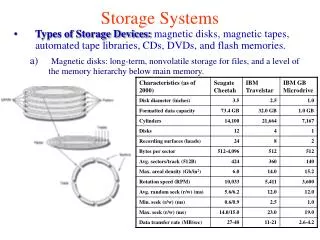
I/O Device Examples Device Behavior Partner Data rate(KB/sec) Keyboard Input Human 0.01 Mouse Input Human 0.02 Line Printer Output Human 1.00 Floppy disk Storage Machine 50.00 Laser Printer Output Human 100.00 Optical Disk Storage Machine 500.00 Magnetic Disk Storage Machine 5,000.00 Network-LAN Input/Output Machine 20 – 1,000.00 Graphics Display Output Human 30,000.00 CS465
Magnetic Disks • Magnetic disks still play the central role in storage systems • Inexpensive • Nonvolatile: DRAM alone cannot replace disk • Relatively fast: compared to tape, recordable CD • But much slower than DRAM CS465
Disk History Data density Mbit/sq. in. Capacity of Unit Shown Megabytes 1973: 1. 7 Mbit/sq. in 140 MBytes 1979: 7. 7 Mbit/sq. in 2,300 MBytes source: New York Times, 2/23/98, page C3, “Makers of disk drives crowd even mroe data into even smaller spaces” CS465
Disk History 1989: 63 Mbit/sq. in 60,000 MBytes 1997: 1450 Mbit/sq. in 2300 MBytes 1997: 3090 Mbit/sq. in 8100 MBytes source: New York Times, 2/23/98, page C3, “Makers of disk drives crowd even more data into even smaller spaces” CS465
Magnetic Disks • Components • Platter, track, sector • Arm, head • Operations • Read/write data is a three-stage process • Seek • Seek time: acceleration, deceleration, stabilization • Wait for the right sector • Rotational delay (0.5/RPS) • Read/transfer • Transfer time: f(density, speed, size) CS465
Magnetic Disk Characteristic • Average seek time as reported by the industry: • Typically in the range of 3 ms to 14 ms • (Sum of the time for all possible seek) / (total # of possible seeks) • Due to locality of disk reference, actual average seek time may only be 25% to 33% of the advertised number • Rotational latency: • Most disks rotate at 5400 to 15000 RPM • Approximately 11 ms to 4 ms per revolution respectively • An average latency to the desired information is halfway around the disk: 5.6 ms at 5400 RPM, 2ms at 15000 RPM CS465
Track Sector Cylinder Platter Head Magnetic Disk Characteristic • Transfer time is a function of : • Transfer size (usually a sector): 1 KB / sector • Rotation speed: 5400 RPM to 15000 RPM • Recording density: bits per inch on a track • Diameter: typical diameter ranges from 2.5 to 5.25 in • Typical transfer speed: 30 to 80 MB per second • Cylinder: all the tracks under the head at a given point on all surface CS465
Disk Layout CS465
Disk Structure • Disk drives are addressed as large 1-dimensional arrays of logical blocks, where the logical block is the smallest unit of transfer. • The 1-dimensional array of logical blocks is mapped into the sectors of the disk sequentially. • Sector 0 is the first sector of the first track on the outermost cylinder. • Mapping proceeds in order through that track, then the rest of the tracks in that cylinder, and then through the rest of the cylinders from outermost to innermost. CS465
Scheduling and Performance • Processor and main memory speeds are several orders of magnitude faster than disk access • Critical that we understand how disks perform • Can scheduling make a difference? • Where are the time sinks for disk access? • Seek time • Rotational Delay • Transfer Delay CS465
Seek Time • This is the time to move the disk arm to the required track. • Comprised of startup time and traversal time. • Seek time S given by S = (m x n) + s where m is a constant, n is the number of tracks traversed and s is the startup time. • Seek times vary but are on the order of a few to about 20 ms CS465
Rotational Delay and Transfer Time • Rotational delay: • About 16.7 ms to complete one entire revolution, so average rotational delay is 8.3 ms. • Transfer delay T is given by T = b/rN where b is the number of bytes to be transferred, N is the number of bytes on a track, and r is the rotation speed in revolutions per second • Total average disk access time A is given by CS465
Example • 512 byte sector, rotate at 5400 RPM, advertised seeks is 12 ms, transfer rate is 4 MB/sec • Basic disk access time = seek time + rotational latency + transfer time • = 12 ms + 0.5 / 5400 RPM + 0.5 KB / 4 MB/s • = 12 ms + 0.5 / 90 RPS + 0.125 / 1024 s • = 12 ms + 5.5 ms + 0.1 ms • = 17.6 ms • If real seeks are 1/3 advertised seeks, then its 9.6 ms, with rotation delay at 50% of the time! • Actual disk access time = Basic disk access time + controller overhead CS465
I/O System Performance • I/O system performance depends on many aspects of the system (“limited by weakest link in the chain”): • CPU • Memory system: • Internal and external caches • Main memory • Underlying interconnection (buses) • I/O controller, I/O device • The speed of the I/O software (OS) • The efficiency of the software’s use of the I/O devices • Two common performance metrics: • Throughput: I/O bandwidth • Response time: latency CS465
Simple Producer-Server Model • Throughput: • The number of tasks completed by the server in unit time • In order to get the highest possible throughput: • The server should never be idle • The queue should never be empty • Response time: • Begins when a task is placed in the queue • Ends when it is completed by the server • In order to minimize the response time: • The queue should be empty • The server will be idle Queue Server Producer CS465
Throughput versus Respond Time Response Time (ms) 300 200 100 20% 40% 60% 80% 100% Percentage of maximum throughput CS465
Throughput Enhancement Server Queue • In general throughput can be improved by: • Throw more hardware at the problem • Reduce load-related latency • Response time is much harder to reduce: • Ultimately it is limited by the speed of light (but we’re far from it) Producer Queue Server CS465
Disk I/O Performance Request Rate Service Rate • Disk access time = seek time + rotational latency + transfer time + controller time + queueing delay • Estimating queue length • Queuing theory • Related to utilization, request rate and service rate Disk Controller Disk Queue Processor Disk Controller Disk Queue CS465
Dependability • How to decide when a system is operating properly? Service Level Agreements (SLA) • Systems alternate between 2 states of service with respect to an SLA: • Service accomplishment, where the service is delivered as specified in SLA (state 1) • Service interruption, where the delivered service is different from the SLA (state 2) • Failure = transition from state 1 to state 2 • Restoration = transition from state 2 to state 1 CS465
Quantify Dependability • Module reliability • A measure of continuous service accomplishment, or equivalently, of the time to failure • Mean Time To Failure (MTTF): reliability in hrs of operation time • Mean Time To Repair (MTTR): service interruption • Mean Time Between Failures (MTBF) = MTTF+MTTR • Module availability • Module availability = MTTF / ( MTTF + MTTR) • A measure of the service accomplishment wrt the alternation between the 2 states of accomplishment and interruption CS465
RAID • Redundant Array of Independent Disks • Applies basic design principle for speed mismatch problem • Go to a parallel solution • 6 levels (RAID 0 - 6) • Broadly defined by • Set of physical disks viewed as a single logical disk • Data distributed across the physical disks in an array • Redundant disk capacity used to store parity information in case of failure (RAID 1 - 6) • 80% of server installations use RAID CS465
Disk Striping • In RAID 0, data are striped across a disk. • User data is views as being stored on a logical disk divided into strips • Stripes can be physical blocks, sectors, etc. • Stripes mapped round robin to consecutive array members. • First n logical strips stored as the first strip on each of the n disks, second n logical strips on each of the n disks, etc. CS465
Disk Striping (2) CS465
RAID 0 • No redundancy • High Data transfer requires smaller strips • Higher IO good for multiple transaction systems CS465
RAID 1 (mirroring) • Achieves redundancy through data duplication. • Allows parallel updates to backups • Simple recovery • Great for reads, but it is expensive overall CS465
RAID 2: fallen into disuse (complex) • Parallel access, all disk members participate in the execution of every I/O request. • Typically requires specialized hardware • Stripes can be byte or word size. • Adds an error correcting code, such as a Hamming code • Number of disks proportional to the log of the number of data disks CS465
RAID 3 • Like RAID 2, except only has one redundant disk • Computes a single parity bit for the set of individual bits in the same position on all disks. • Let X4 be the parity disk, and X0 to X3 be the data disks. Then the parity for the ith bit is Suppose X1 fails. Then add X4(i) XOR X1(i) CS465
RAID 3 (2) • Small strips make high data transfer rates possible CS465
RAID 4 • Each disk operates independently • Good for high I/O request rates, not so good for high data transfer requirements • Bit-by-bit parity calculated and stored on the parity disk (like in RAID 3) • Each write involves the parity disk. CS465
RAID 5 • Like RAID 4 except the parity strip is across all disks. Avoids write bottleneck CS465
RAID 6 • Parity protects against single failure • It can be generalized to have a second calculation over the data and another check disk • Allows recovery from a second failure: RAID 6 • Rarely used CS465
Outline • Storage • Disk performance • Seek time, rotation latency, transfer time • I/O performance • Throughput, latency • Dependability, reliability, availability • Bus • I/O device interfacing CS465
Processor Input Control Memory Datapath Output What Is a Bus? • A bus is: • Shared communication link • Single set of wires used to connect multiple subsystems • A bus is also a fundamental tool for composing large, complex systems • Systematic means of abstraction CS465
Memory Processer Advantages of Buses • Versatility: • New devices can be added easily • Peripherals can be moved between computersystems that use the same bus standard • Low cost: • A single set of wires is shared in multiple ways I/O Device I/O Device I/O Device CS465
Memory Processer Disadvantage of Buses • It creates a communication bottleneck • The bandwidth of that bus can limit the maximum I/O throughput • The maximum bus speed is largely limited by: • The length of the bus • The number of devices on the bus • The need to support a range of devices with: • Widely varying latencies • Widely varying data transfer rates I/O Device I/O Device I/O Device CS465
The General Organization of a Bus Control Lines Data Lines • Control lines: • Signal requests and acknowledgments • Indicate what type of information is on the data lines • Data lines carry information between the source and the destination: • Data and addresses • Complex commands • A bus transaction includes two parts: • Issuing the command (and address) – request • Transferring the data – action CS465
Types of Buses • Processor-Memory Bus (design specific) • Short and high speed • Only need to match the memory system • Maximize memory-to-processor bandwidth • Optimized for cache block transfers • I/O Bus (industry standard) • Usually lengthy and slower • Need to match a wide range of I/O devices • Connects to the processor-memory or backplane bus • Backplane Bus (standard or proprietary) • Backplane: an interconnection structure within the chassis • Allow processors, memory, and I/O devices to coexist • Cost advantage: one bus for all components CS465
Example: Pentium Organization Processor/Memory Bus PCI Bus I/O Busses CS465
Backplane Bus Backplane Bus Processor Memory • A single bus (the backplane bus) is used for: • Processor to memory communication • Communication between I/O devices and memory • Advantages: simple and low cost • Disadvantages: slow and the bus can become a major bottleneck • Example: IBM PC - AT I/O Devices CS465
Processor Memory Bus Processor Memory Bus Adaptor Bus Adaptor Bus Adaptor I/O Bus I/O Bus I/O Bus A Two-Bus System • I/O buses tap into the processor-memory bus via bus adaptors: • Processor-memory bus: mainly for processor-memory traffic • I/O buses: provide expansion slots for I/O devices • Apple Macintosh-II • NuBus: processor, memory, and a few selected I/O devices • SCCI Bus: the rest of the I/O devices CS465
Processor Memory Bus Processor Memory Bus Adaptor Backside Cache bus Bus Adaptor I/O Bus L2 Cache I/O Bus Bus Adaptor A Three-Bus System • A small number of backplane buses tap into the processor-memory bus • Processor-memory bus is only used for processor-memory traffic • I/O buses are connected to the backplane bus • Advantage: loading on the processor bus is greatly reduced CS465
Synchronous/Asynchronous Bus • Synchronous Bus: • Includes a clock in the control lines • A fixed communication protocol relative to the clock • Advantage: involves very little logic; can run very fast • Disadvantages: • Every device on the bus must run at the same clock rate • To avoid clock skew, bus cannot be long if they are fast • Asynchronous Bus: • It is not clocked • It can accommodate a wide range of devices • It can be lengthened w/o worrying about clock skew • It requires a handshaking protocol • Needs additional set of control lines CS465
Asynchronous Handshaking Protocol Figure 8.10: 7 steps to read a word from memory and receive it in an I/O device 4. This starts when the memory has the data ready. It places the data from the read request on the data lines and raises DataRdy 3. Memory sees that ReadReq is low and drops the Ack line to acknowledge the Read Req signal 5. The I/O sees DataRdy, reads the data from the bus, and signals that it ahs the data by raising Ack. 6. The memory sees the Ack signal, drops DataRdy, and releases the data lines. 7. Finally, the I/O devices, seeing DataRdy go low, drops the Ack line, which indicates that the transmission is completed. • When memory sees the ReadReq line, it reads the address from the data bus • and raises Ack to indicate it has been seen. 2. I/O device sees the Ack line high and releases the ReadReq and data lines. CS465
Outline • Storage • Bus • Important technique for building large-scale systems • Different types of buses • Two types of bus timing: • Synchronous: bus includes clock • Asynchronous: no clock, just REQ/ACK • I/O device interfacing CS465
Responsibilities of OS • The operating system acts as the interface between: • The I/O hardware and the program that requests I/O • Three characteristics of the I/O systems: • The I/O system is shared by multiple programs using the processor • I/O systems often use interrupts (external generated exceptions) to communicate information about I/O operations. • Interrupts must be handled by the OS because they cause a transfer to supervisor mode • The low-level control of an I/O device is complex: • Managing a set of concurrent events • The requirements for correct device control are very detailed CS465
Required Functions of OS • Provide protection to shared I/O resources • Guarantee that a user’s program can only access theportions of an I/O device to which the user has rights • Provides abstraction for accessing devices: • Supply routines that handle low-level device operation • Handles the interrupts generated by I/O devices • Provide equitable access to the shared I/O resources • All user programs must have equal access to the I/O resources • Schedule accesses in order to enhance system throughput CS465
Communication Requirements • The operating system must be able to prevent: • The user program from communicating with the I/O device directly • If user programs could perform I/O directly: • Protection to the shared I/O resources could not be provided • Three types of communication are required: • The OS must be able to give commands to the I/O devices • The I/O device must be able to notify the OS when the I/O device has completed an operation or has encountered an error • Data must be transferred between memory and an I/O device CS465