Download
1 / 1
10 likes | 162 Views
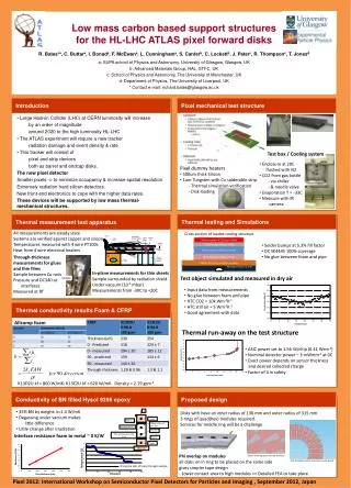
Q. Low mass carbon based support structures for the HL-LHC ATLAS pixel forward disks. Copper. Glue 1. 500µm of hysol + 35% BN. Silicon readout IC (150 μm thick). Allcomp foam. Sensors. Solder bumps (20 μm thick ). Glue penetrated into the foam. Anchor. Aluminium thermal shield.

E N D
Q Low mass carbon based support structures for the HL-LHC ATLAS pixel forward disks Copper Glue 1 500µm of hysol + 35% BN Silicon readout IC (150 μm thick) Allcomp foam Sensors Solder bumps (20 μm thick) Glue penetrated into the foam Anchor Aluminium thermal shield Silicon detector (300 μm thick) Heater wires Shield heater Pt100 wires Glue 2 Sample heater Pt100_5 DC SE4445 gel (200 μm thick) Copper 1 2 3 4 Sample Heat sink R. Bates*a, C. Buttara, I. Bonada, F. McEwana, L. Cunninghama, S. Canferb, C. Lockettb, J. Paterc, R. Thompsonc, T. Jonesd a: SUPA school of Physics and Astronomy, University of Glasgow, Glasgow, UK b: Advanced Materials Group, RAL, STFC, UK c: School of Physics and Astronomy, The University of Manchester, UK d: Department of Physics, The University of Liverpool, UK * Contact e-mail: richard.bates@glasgow.ac.uk CFRP K13C2U 50 gsm (200 μm thick) Heat sink Pt100_6 Plastic insulation supports Allcomp Foam (2.3 mm thick) Water cooled H2O Introduction Pixel mechanical test structure • Large Hadron Collider (LHC) at CERN luminosity will increase • by an order of magnitude • around 2020 to the high luminosity HL-LHC • The ATLAS experiment will require a new tracker • radiation damage and event density & rate • This tracker will consist of • pixel and strip devices • both as barrel and endcap disks. • The new pixel detector • Smaller pixels -> to minimize occupancy & increase spatial resolution • Extremely radiation hard silicon detectors. • New front-end electronics to cope with the higher data rates. • These devices will be supported by low mass thermal-mechanical structures. Test box / Cooling system • Enclosure at 20C • flushed with N2 • CO2 from gas bottle • - via chiller • - & needle valve • Evaporation T = -33C • Measure with IR • camera • Pixel dummy heaters • 500um thick Silicon • 1um Tungsten with Cu solderable strip • - Thermal simulation verification • - Disk loading Thermal testing and Simulations Thermal measurement test apparatus All measurements are steady state Systems are verified against copper and silicon Temperatures measured with 4 wire PT100s Heat from 4 wire electrical heaters Cross-section of loaded cooling structure • Solder bumps at 5.3% fill factor • DC SE4445 100% coverage • No glue between foam and pipe Through-thickness measurements for glues and thin films Sample between Cu rods Pressure and DC340 at interfaces Measured at RT In-plane measurements for thin sheets Sample surrounded by radiation shield Under vacuum (10-5 mbar) Measurements from -30C to +20C Test object simulated and measured in dry air Sample • Input data from measurements • No glue between foam and pipe • HTC CO2 = 10k Wm-2K-1 • HTC still air = 5 Wm-2K-1 • Good agreement with data Thermal conductivity results Foam & CFRP Allcomp foam Thermal run-away on the test structure • ASIC power set to 1.56 W/chip (0.41 Wcm-2) • Nominal detector power ~ 3 mWmm-2 at 0C • Exact power depends on sensor thickness • and desired collected charge • Factor of 4 in safety K13D2U kf = 800 W/mK: K13C2U kf = 620 W/mK. Density = 2.19 gcm-3 Conductivity of BN filled Hysol 9396 epoxy Proposed design • 35% BN by weight: k=1.4 W/mK • Degassing under vacuum makes • little difference • Little change after irradiation Disks with have an inner radius of 130 mm and outer radius of 315 mm 3 rings of quad(hex) modules required. Services for middle ring will be a challenge Interface resistance foam to metal ~ 0 K/W Phi overlap on modules all disks on in ring to be placed on the same side gives simpler tape design - Lower contact area to high modules => Detailed FEA to take place Zoom showing space around modules Temperature (C) Disk 4 Mixed module sizes (Hex, quad, quad) IR camera plot of temp through sample Distance Pixel 2012: International Workshop on Semiconductor Pixel Detectors for Particles and Imaging , September 2012, Japan