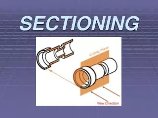
Sectioning
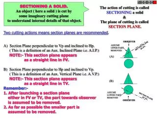
Sectioning. ERT 243/3 CAD IN BIOSYSTEM ENGINEERING. SITI KAMARIAH BINTI MD SA’AT SCHOOL OF BIOPROCESS ENGINEERING, UNIMAP. Sectioning. There are many times when the interior details of an object cannot be seen from the outside. .

Sectioning
E N D
Presentation Transcript
Sectioning ERT 243/3 CAD IN BIOSYSTEM ENGINEERING SITI KAMARIAH BINTI MD SA’AT SCHOOL OF BIOPROCESS ENGINEERING, UNIMAP
Sectioning • There are many times when the interior details of an object cannot be seen from the outside. Page 2
It should not really be a surprise that a convention is required to give additional detailsabout the interior of an object. Many common examples can be seen every day - items that lookas though they may be constructed In similar ways when viewed solely with the informationavailable from the outer surface. Page 3
We can get around this by pretending to cut the object on a plane and showing the "sectional view". The sectional view is applicable to objects like engine blocks, where the interior details are intricate and would be very difficult to understand through the use of "hidden" lines (hidden lines are, by convention, dotted) on an orthographic or isometric drawing. • Imagine slicing the object in the middle Page 4
Take away the front half and what you have is a full section view Page 9
A cross-sectional view portrays a cut-away portion of the object and is another way to show hidden components in a device. • Imagine a plane that cuts vertically through the center of the pillow block. Then imagine removing the material from the front of this plane. Page 11
This is how the remaining rear section would look. Diagonal lines (cross-hatches) show regions where materials have been cut by the cutting plane. Page 13
This cross-sectional view (section A-A) one that is orthogonal to the viewing direction, shows the relationships of lengths and diameters better. • The top "outside" view of the bearing is shown in next fifure. It is an orthogonal (perpendicular) projection. Notice the direction of the arrows for the "A-A" cutting plane. Page 14
The top "outside" view of the bearing Page 15
Half-Sections • A half-section is a view of an object showing one-half of the view in section. • The diagonal lines on the section drawing are used to indicate the area that has been theoretically cut. Page 16
Half-Sections • These lines are called section lining or cross-hatching. The lines are thin and are usually drawn at a 45-degree angle to the major outline of the object. • The spacing between lines should be uniform. A second, rarer, use of cross-hatching is to indicate the material of the object. One form of cross-hatching may be used for cast iron, another for bronze, and so on. Page 17
Full and sectioned isometric views Page 18
Front view and half section Page 19
Cross section Page 20
EXAMPLE 1: Page 21
EXAMPLE 2: Page 22
EXAMPLE 3: Page 23
EXAMPLE 4: Page 24