Object-oriented Design
Object-oriented Design. Objectives. To explain how a software design may be represented as a set of interacting objects that manage their own state and operations To describe the activities in the object-oriented design process

Object-oriented Design
E N D
Presentation Transcript
Objectives • To explain how a software design may be represented as a set of interacting objects that manage their own state and operations • To describe the activities in the object-oriented design process • To introduce various models that can be used to describe an object-oriented design • To show how the UML may be used to represent these models
Topics covered • Objects and object classes • An object-oriented design process • Design evolution
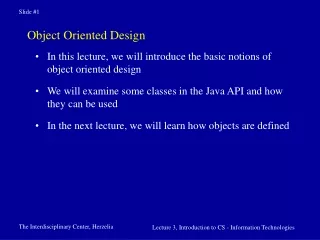
Object-oriented development • Object-oriented analysis, design and programming are related but distinct. • OOA is concerned with developing an object model of the application domain. • OOD is concerned with developing an object-oriented system model to implement requirements. • OOP is concerned with realising an OOD using an OO programming language such as Java or C++.
Characteristics of OOD • Objects are abstractions of real-world or system entities and manage themselves. • Objects are independent and encapsulate state and representation information. • System functionality is expressed in terms of object services. • Shared data areas are eliminated. Objects communicate by message passing. • Objects may be distributed and may execute sequentially or in parallel.
Advantages of OOD • Easier maintenance. Objects may be understood as stand-alone entities. • Objects are potentially reusable components. • For some systems, there may be an obvious mapping from real world entities to system objects.
Objects and classes An object is an entity that has a state and a defined set of operations which operate on that state. The state is represented as a set of object attributes. The operations associated with the object provide services to other objects (clients) which request these services when some computation is required. Objects are created according to some object class definition. An object class definition serves as a template for objects. It includes declarations of all the attributes and services which should be associated with an object of that class.
Object communication • Conceptually, objects communicate by message passing. • Messages • The name of the service requested by the calling object; • Copies of the information required to execute the service and the name of a holder for the result of the service. • In practice, messages are often implemented by procedure calls • Name = procedure name; • Information = parameter list.
Generalisation and inheritance • Objects are members of classes that define attribute types and operations. • Classes may be arranged in a class hierarchy where one class (a super-class) is a generalisation of one or more other classes (sub-classes). • A sub-class inherits the attributes and operations from its super class and may add new methods or attributes of its own. • Generalisation in the UML is implemented as inheritance in OO programming languages.
Advantages of inheritance • It is an abstraction mechanism which may be used to classify entities. • It is a reuse mechanism at both the design and the programming level. • The inheritance graph is a source of organisational knowledge about domains and systems.
Problems with inheritance • Object classes are not self-contained. they cannot be understood without reference to their super-classes. • Designers have a tendency to reuse the inheritance graph created during analysis. Can lead to significant inefficiency. • The inheritance graphs of analysis, design and implementation have different functions and should be separately maintained.
The Unified Modeling Language • Several different notations for describing object-oriented designs were proposed in the 1980s and 1990s. • The Unified Modeling Language is an integration of these notations. • It describes notations for a number of different models that may be produced during OO analysis and design. • It is now a de facto standard for OO modelling.
Concurrent objects • The nature of objects as self-contained entities make them suitable for concurrent implementation. • The message-passing model of object communication can be implemented directly if objects are running on separate processors in a distributed system.
Servers and active objects • Servers. • The object is implemented as a parallel process (server) with entry points corresponding to object operations. If no calls are made to it, the object suspends itself and waits for further requests for service. • Active objects • Objects are implemented as parallel processes and the internal object state may be changed by the object itself and not simply by external calls.
Active transponder object • Active objects may have their attributes modified by operations but may also update them autonomously using internal operations. • A Transponder object broadcasts an aircraft’s position. The position may be updated using a satellite positioning system. The object periodically update the position by triangulation from satellites.
An active transponder object class Transponder extends Thread { Position currentPosition ; Coords c1, c2 ; Satellite sat1, sat2 ; Navigator theNavigator ; public Position givePosition () { return currentPosition ; } public void run () { while (true) { c1 = sat1.position () ; c2 = sat2.position () ; currentPosition = theNavigator.compute (c1, c2) ; } } } //Transponder
Java threads • Threads in Java are a simple construct for implementing concurrent objects. • Threads must include a method called run() and this is started up by the Java run-time system. • Active objects typically include an infinite loop so that they are always carrying out the computation.
Topics covered • Objects and object classes • An object-oriented design process • Design evolution
Some UML modeling notations • Use case diagram • Class diagram • Sequence diagram • Statechart diagram • Activity diagram • Deployment diagram • Component diagram • Collaboration diagram
UML associations • Objects and object classes participate in relationships with other objects and object classes. • In the UML, a generalised relationship is indicated by an association. • Associations may be annotated with information that describes the association. • Associations are general but may indicate that an attribute of an object is an associated object or that a method relies on an associated object.
An object-oriented design process • Structured design processes involve developing a number of different system models. • They require a lot of effort for development and maintenance of these models and, for small systems, this may not be cost-effective. • However, for large systems developed by different groups design models are an essential communication mechanism.
Process stages • Highlights key activities without being tied to any proprietary process such as the RUP. • Define the context and modes of use of the system; • Design the system architecture; • Identify the principal system objects; • Develop design models; • Specify object interfaces.
Running example: Simple personnel information system • Design a simple information system to support a personnel manager. • Features include the ability to add, query and delete personnel in a database.
System context and models of use • Develop an understanding of the relationships between the software being designed and its external environment • System context • A static model that describes other systems in the environment. Use a subsystem model to show other systems. • Model of system use • A dynamic model that describes how the system interacts with its environment. Use use-cases to show interactions
Use-case models • Use-case models are used to represent each interaction with the system. • A use-case model shows the system features as ellipses and the interacting entity as a stick figure. • Flow of events within a use case can be depicted using sequence diagrams.
Use cases for the personnel information system The diagram is only part of the story. Need to also develop use case descriptions (not shown here).
Sequence models • Uses • OOA – depict flow of events within a use case; helps identify initial objects • OOD – depict interactions of objects; helps identify methods and other attributes and classes • Review • Objects are arranged horizontally across the top; • Time is represented vertically so models are read top to bottom; • Interactions are represented by labelled arrows, Different styles of arrow represent different types of interaction; • A thin rectangle in an object lifeline represents the time when the object is the controlling object in the system.
Object identification • Identifying objects (or object classes) is the most difficult part of object oriented analysis and design. • There is no 'magic formula' for object identification. It relies on the skill, experience and domain knowledge of system designers. • Object identification is an iterative process. You are unlikely to get it right first time.
Approaches to identification • Use a grammatical approach based on a natural language description of the system. • Base the identification on tangible things in the application domain. • Use a behavioural approach and identify objects based on what participates in what behaviour. • Use a scenario-based analysis. The objects, attributes and methods in each scenario are identified.
Application domain objects Initial class diagram derived from the behavioral models (sequence diagrams).
Architectural design • Once interactions between the system and its environment have been understood and initial objects have been identified, you use this information for designing the system architecture. • A layered architecture as discussed in Chapter 11 is appropriate for the information system • User interface layer for handling interactions; • Application logic layer for controlling data access and updates; • Data management layer for storing data. • There should normally be no more than 7 subsystems in an architectural model.
Design models • Design models show the objects and object classes and relationships between these entities. • Static models describe the static structure of the system in terms of object classes and relationships. • Dynamic models describe the dynamic interactions between objects.
Examples of design models • Sub-system models that show logical groupings of objects into coherent subsystems. • Sequence models that show the sequence of object interactions. • State machine models that show how individual objects change their state in response to events. • Other models include use-case models, aggregation models, generalisation models, etc.
Subsystem models • Shows how the design is organised into logically related groups of objects. • In the UML, these are shown using packages - an encapsulation construct. This is a logical model. The actual organisation of objects in the system may be different.
Application domain objects (Initial class diagram)
Subsystem decomposition In this case, each layer is one subsystem. In general, a layer can have more than one subsystem.
Distribution strategy (Deployment diagram)
Platforms and implementation technologies (Deployment diagram)
Further objects and object refinement • Use domain knowledge to identify more objects and operations • What attributes should be included in a personnel database? • What other checking should be done before allowing a deletion? • Use software development knowledge to identify solution objects • Design patterns often add more abstract classes. • Performance issues may require the use of proxy objects to cache some of the database in memory • What other widgets need to be defined on the personnel form?
Static model – class diagram Includes objects from solution domain.
Static model – more details Expand class attributes and operations.
Dynamic models • Sequence models • Show interaction between objects • Statechart models • Show transitions within an object
Object interface specification • Object interfaces have to be specified so that the objects and other components can be designed in parallel. • Designers should avoid designing the interface representation but should hide this in the object itself. • Objects may have several interfaces which are viewpoints on the methods provided. • The UML uses class diagrams for interface specification but Java may also be used. • Heuristic: figure out how you plan to divide the work, and specify the interfaces between the divisions.
Database interface • An interface can be defined to hide the details of how the underlying database tables are organized. interface class DatabaseInterface { public void AddPersonnel(); public void DeletePersonnel(); public void queryPersonnel() } public class ProxyDatabaseInterface implements DatabaseInterface { … } public class RealDatabaseInterface implements DatabaseInterface { … }