Download
1 / 27
390 likes | 844 Views
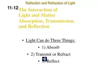
Light-Matter Interaction in Nanophotonics. Peter Lodahl DTU Fotonik , Dept. of Photonics Engineering, Technical University of Denmark. www.fotonik.dtu.dk/quantumphotonics. Atoms versus Quantum Dots. Quantum dots are ’artificial atoms’. Atom. Quantum dot. InAs. GaAs. conduction band.

E N D
Light-MatterInteraction in Nanophotonics Peter Lodahl DTU Fotonik, Dept. of Photonics Engineering, Technical University of Denmark. www.fotonik.dtu.dk/quantumphotonics
Atoms versus Quantum Dots Quantum dots are ’artificial atoms’ Atom Quantum dot InAs GaAs
conduction band electron states InAs GaAs e- hole states h+ valence band Requirement to have quantum dots: QD radius exciton Bohr radius Quantum dots: solid state single-photon source GaAs surface InAs quantum dot 300 nm CdSe quantum dot
2-band effective-mass model for electrons and • holes (Bloch part of wavefunction). InAs (very) Simple quantum dot models Simplifying assumptions: • Spherical potential well, infinite barriers (U0 ) • (envelope part of wavefunction). U0 0 r R
The electron and hole energy levels: reduced e-h mass dielectric constant of barrier material e, 1p Ee Selection rule for photon emission: lh = le e, 1s Eg+DE h, 1s h, 1p Eh Wavefunctions and energies The envelope wavefunctions are obtained by solving the Schrödinger equation for ‘a particle in a box’ For more realistic models with comparison to experiments, see: S. Stobbe, J. Johansen, P.T. Kristensen, J.M. Hvam & P. Lodahl, arXiv:cond-mat 0902.0344v1 (see: www.fotonik.dtu.dk/quantumphotonics)
Relaxation p s GaAs bandgap InAs bandgap s Homogeneous linewidth of single QDs: p decay pure dephasing Optical properties of quantum dots
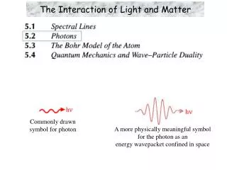
w2,k2 w4,k4 |a> wab |b> w3,k3 w1,k1 The interaction Hamiltonian due to coupling between a 2-level system and a multimode electric field: The total Hamiltonian is given by EM field coupling dipole where Light-matter interaction: the 2-level emitter
|a> w,kj wab |b> The equations of motion are obtained from the Schrödinger equation: equations of motion where Equations of motion for 2-level system emitting a photon Restrict to the situation where the 2-level system starts in the excited state and can emit a single photon in an arbitrary direction (i.e. spon. emission)
|a> w,kj wab |b> Wigner-Weisskopf approximation: Population of excited state decays exponen- tially in time. Wigner-Weisskopf theory of spontaneous emission Integrating the equations of motion assuming ca(0)=1 leads to: Integrating the equations of motion assuming ca(0)=1 leads to:
Time-resolved spontaneous emission from quantum dots Spontaneous emission from quantum dots decays exponentially according to Wigner-Weisskopf theory van Driel et al., Phys. Rev. Lett. 95, 236804 (2005).
Mode volume: Cavity quality factor: Rate of cavity damping: SE into other modes: Exchange of energy between emitter and cavity occurs at the Rabi frequency: A quantum dot in a cavity Quantized EM cavity field:
Cavity figure of merit Vahala, Nature 424, 839 (2003). Figure of merit for the cavity: Q/V No need to increase Q further than:
(cf. exercise) 2-level emitter in a cavity: The Rabi model |e> wc= w0=w |g> Exclude for the moment dissipation (==0) Note: slight change of notation
Solutions to the Rabi model Population oscillates between excited state and ground state (Rabi oscillations) n=0: vacuum Rabi oscillations
(cf. exercise) Eigenenergies of the coupled system. QDs at low temperature: Typical Q-factors (103-106): For moderate Q-factors: Including cavity and emitter dissipation Restrict to n=0 and include also dissipation of cavity and emitter:
Frequency Damping emitter weak strong weak strong cavity e.g. increasing Q Strong and weak coupling regimes Strong coupling: Weak coupling:
strong damping: cavity emitter Decay rate for population of emitter in the cavity: Decay rate in a homogeneous medium: Enhancement of rate in the cavity: Purcell factor Fp The Purcell effect (weak coupling regime) Weak coupling:
Experimental demonstration of the Purcell effect Wigner-Weisskopf theory of spontaneous emission: Gerard et al., Phys. Rev. Lett. 81, 1110 (1998).
Experimental demonstration of strong coupling Nano-cavity based on photonic crystal defect Q = 13000 V ~ 0.04 m3 Quantum dots as light emitters Yoshie et al., Nature, vol. 432, p. 200, Nov. 2004
Experimental demonstration of strong coupling II High pump power: cavity resonance Avoided crossing when cavity is tuned relative to quantum dot (by temperature). Yoshie et al., Nature, vol. 432, p. 200, Nov. 2004
Inhibited spontaneous emission in band gap. • Enhanced density of states enhanced emission. Yablonovitch, Phys. Rev. Lett. 58, 2059 (1987). Photonic crystals a l Periodic dielectric structure scale a wavelength of light l
k 2D: Membranes, fibers 3D: Opals, inverse opals Photonic Crystals in 1D, 2D, and 3D 1D: Bragg grating Spontaneous emission control requires 3D confine- ment of light (not necessarily 3D photonic crystals)
Spontaneous emission in a photonic crystal Spontaneous emission decay depends on position in the photonic crystal The decay rate is proportional to the projected local density of states within Wigner-Weisskopf theory: emitter environment Change LDOS with photonic crystal decay rate of emitter can be controlled.
The total density of optical states (DOS) (fcc lattice of air-spheres, ~12) Busch&John, Phys. Rev. E 58, 3896 (1998) Frequency Wavevector
DOS is the unit-cell averaged LDOS: LDOS is strongly modified in a photonic crystal: Koenderink et al., Opt. Lett. 30, 3210 (2005). The local density of optical states (LDOS) Decay rate of emitters is determined by the LDOS that contains the local electric field at the position of the emitter:
gMF = 0.052 ns-1 gMF= 0.081 ns-1 gMF= 0.104 ns-1 (inhibition) (reference) (enhancement) Experimental demonstration of spontaneous emission control CdSe quantum dots Titania 3D photonic crystal ‘inverse opal’ Lodahl, van Driel, Nikolaev, Irman, Overgaag, Vanmaekelberg & Vos, Nature 430, 654 (2004).
LDOS calc. experiment Photonic crystal membranes 2D photonic crystals control light in 3D since light is guided by total-internal-reflection due the membrane experimentally favorable configuration since quantum dots can be addressed from above Julsgaard, Johansen, Stobbe, Rohr, Sünner, Kamp, Forchel & Lodahl, Appl. Phys. Lett. 93, 094102 (2008).