Download
1 / 18
180 likes | 334 Views
This document discusses the implementation and operational strategies for the Advanced Damping Technology (ADT) aimed at increasing bandwidth within particle accelerators. It details the ADT’s feedback mechanism using transverse dampers, including critical components such as beam position monitors and electrostatic kickers. The paper highlights the enhancements made to frequency response, enabling faster damping of beam oscillations. Preliminary results show promising bandwidth increases while maintaining high gain, though further optimization and noise management are essential for future operational efficiency.

E N D
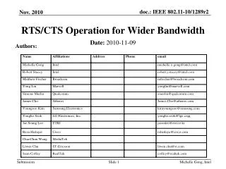
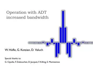
Operation with ADT increased bandwidth W. Höfle, G. Kotzian, D. Valuch Special thanks to: G. Cipolla, F. Dubouchet, D. Jacquet, F. Killing, E. Montesinos
The transverse damper in general • The transverse damper is a feedback system: it measures the bunch oscillations and damps them by fast electrostatic kickers • Key elements: • Beam position monitor(s) • Signal processing system • Power amplifiers • Electrostatic kickers Tbeam • Key parameters: • Feedback loop gain, phase and delay • Kick strength • Bandwidth Tsignal
ADT Frequency response • Power amplifiers, 1st order low pass, -3 dB @ 1 MHz • Power amplifier phase response compensated by digital filter Frequency domain measurements February 2012 B. Lojko. Step response measurements 19.9.2012 D.Valuch, G.Kotzian kick @ 10 MHz, 10% strength left
Impulse response • Phase compensation makes the impulse response symmetric and removes the exponential tail
Frequency response/damping time • Consequence: “crosstalk” and different damping time for different bunches within the train Damping time for individual bunches within the 144b train. Injection oscillation fill 2676, 2nd injection New injection 144b 12b already circulating
Frequency response/damping time • Damping of individual bunches in case they become unstable still follows the system frequency response: • -3 dB point at 1 MHz • i.e. 10% strength available at 10MHz if two adjacent bunches oscillate in anti-phase (50ns beam)
Damping of single bunch instabilities • Impulse response of damper spreads oscillation to adjacent bunches • Simulation with simplified damper model (no delays, ideal system) • A train of 48 bunches, 25ns bunch spacing • Random initial conditions in amplitude and phase for all bunches • 1 bunch is unstable (rise time of 300 turns)
Standard bandwidth High bandwidth A train of 48 bunches, 25ns, random initial conditions for all bunches, 1 bunch is unstable
Enhancement of the frequency response • The full power is needed only for efficient injection oscillation damping, damper uses <1% of its strength otherwise • Small signal response could be enhanced by drive signal pre-distortion • Once commissioned, enhanced bandwidth should provide faster damping of high frequency modes • “Ideal damper” – could treat each bunch individually • Potential drawback – increase of noise injected through the damper • System more sensitive to precise setting up and drifts
Enhancement of the frequency response • Drive signal pre-distortion enhances the frequency response up to 25 MHz (with symmetric roll off) 25 15
Enhancement of the frequency response • Symmetric roll off in frequency domain will eliminate the bunch by bunch crosstalk
Enhancement of the frequency response • Measured enhanced frequency response reaches beyond 20 MHz Bunch by bunch damper! 12dB needs to be compen- sated for same damping time
Enhancement of the frequency response • Measured enhanced frequency response reaches beyond 20 MHz Bunch by bunch damper!
Commissioning and operation • The high bandwidth operation was commissioned for 25ns operation, including proper setting up with beam • Settings for 50ns operation were not yet optimized • need 1-2 hours at injection to fine adjust the one-turn delay • measure the damping time • quantify the noise behaviourw.r.t. standard operation • Preliminary results are very encouraging • Demonstrated increase of bandwidth while maintaining the high gain
Operational experience with 50ns beam • High BW operation was already tested through the cycle • Since fill 3212: High BW during the squeeze up to collision than back to “standard” bandwidth Plot and table G. Arduini High BW ADT during stable beams
Operational experience with 50ns beam • High BW operation was already tested through the cycle • Since fill 3212: High BW during the squeeze up to collision than back to “standard” bandwidth Plot and table G. Arduini High BW ADT during stable beams More benchmarking required to understand and optimize the performance
Summary • For operational modes where the full kick strength is not needed the ADT frequency response could be enhanced to provide “bunch-by-bunch” damper while keeping the gain high • Method proved to be valid, already part of the LHC cycle (High BW during the squeeze up to collision). Implemented as a sequencer task • Enhanced response could have a potential drawback – increase of noise injected through the damper needs to be studied • Wide bandwidth system is less tolerant to imperfections in settings (such as the 1-turn delay) • Input for our LS1 upgrade activities: • Noise reduction is important for high BW operation • Precise control of frequency response up to 25 MHz