B-14
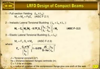
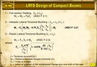
LRFD Design of Compact Beams. 1 – Full section Yielding (L b ≤ L p ): M n = M p = FyZ x (AISC F 2.1) 2 – Inelastic Lateral Torsional Buckling ( L p < L b ≤ L r ): 3 – Elastic Lateral Torsional Buckling (L r < L b ): M n = F cr S x ≤ M p (AISC F-2.3) where:.

B-14
E N D
Presentation Transcript
LRFD Design of Compact Beams 1 – Full section Yielding (Lb ≤ Lp): Mn = Mp = FyZx (AISC F 2.1) 2 – Inelastic Lateral Torsional Buckling ( Lp < Lb ≤ Lr ): 3 – Elastic Lateral Torsional Buckling (Lr < Lb): Mn = Fcr Sx ≤ Mp (AISC F-2.3) where: J = Torsional constant (in4). ho = Distance between flanges centroids (in). C = 1.0 for w shapes. rts = radius of gyration of the compression flange plus one-sixth of the web. B-14
(Cb) Moment Gradient Factor Equations (F 2.2) & (F2.4) for compact beams affected by lateral torsional buckling, require the introduction of the “Moment Gradient Factor” (Cb) for non-uniform bending moment values between the lateral bracing points for (Lb). AISC provides value for Cb as: The effect of Cb on Nominal Strength is shown below: B-15
(Cb) Examples on Moment Gradient Factor Example B - 5 Determine (Cb) for a uniformly loaded, simply supported beam with lateral supports at its ends only. Solution B-16
(Cb) Some Examples on For unbraced cantilever beams, AISC recommends the value of Cb = 1.0. A value of Cb = 1.0 is always conservative and represent uniform banding throughout the unbraced length (Lb), (See Table 3-1) AISC. B-17
Example on Bending of Compact Sections Example B - 6 • Determine the design strength (b Mn) for W14 68 made of A-572-Gr50 steel and: • Continuous lateral support. • Unbraced length = 20 ft, Cb = 1.0 • Unbraced length = 20 ft, Cb = 1.75 Solution A) Check compactness: web is always compact ! Mn = Mp = FyZ = 20 115 = 5750 in·k = 479 ft·k. b Mn = 0.9 479 = 431 ft·k. B) B-18
Continued: Since Lp < (Lb = 20 ft) < Lr Equation F – 2.2 controls: b Mn = 0.9 316.25 = 284.6 ft·kip. • For Cb = 1.75, other conditions unchanged: • Mn = 1.75 316.25 = 553.4 ft·k. • Since Mn ≤ Mp, • then Mn = Mp = 479 ft·k • bMn = 0.9 479 =431 ft·k. B-19
w L = 20 ft Design of Un-braced Beams Example B - 7 A simply supported beam of span = 20ft is to carry static dead load of (1.0 k/ft) and a live load of (2.0 k/ft) in addition to its own dead weight. The flange is laterally supported at support points only. Select the most economical W shape using A572-Gr50 steel. Solution Estimate self weight = 0.06 k/ft. Wu = 1.2 x 1.06 + 1.6 x 2 = 4.47 k/ft Check your selection: From Load Factor Design Selection Table 3.2 in AISC (page 3-17) : Zx = 77.9 in3 , Lp = 8.76 ft , Lr = 28.2 ft. Determine (Cb) for UDL = 1.14 (see B-16) bMn Mu bMn 224 k.ft Enter Beam Design Moments Chart at AISC for Lb = 20 ft, and bMn = 234, select: W12 x 53 (page 3.126 but for Cb = 1.0) B-20
Design Problem Contd.. Since Lp<(Lb=20 ft) < Lr then : equation ( F-2 – 2b AISC) where Cb = 1.14 Mp = FyZx = 50x77.9 = 3895 k. in = 324.6 k·ft. Sx = 70.6 in3 bMn = 0.9 x 292 = 262.7 (Mu = 223.6 k·ft) OK B-21
Bending Strength of Non-compact Sections As noted earlier, most W,M & S shapes are compact for Fy = 36 ksi and Fy = 50 ksi , very few sections are non-compact because of their flanges, but non are slender. The effect of non-compact flange is recognized in the AISC as the smaller value of LTB (AISC F 2.2) and where B-22
Non – Compact Flange Section Example B - 8 A simple supported beam with span = 45 ft is laterally supported at ends only , and is subject to the following service loading: D.L. = 0.4 k/ft ( including self wt.) L.L = 0.7 k/ft Is W 14 x 90 made of A572-Gr50 steel adequate? Solution Wu = 1.2 x 0.4 = 1.6 k·ft B-23
Non – Compact Flange Section Contd. p < < r The shape is non-compact. Section properties: Zx = 157 in3 , Sx = 143 in3 (properties 1) Lp = 15.2 ft, Lr = 42.6 ft (Table 3.2 p. 3.16) • Now we check the capacity due to LTB: Lr < ( Lb = 45 ft) Elsatic LTB controls bMn = 0.9 x 638.2 = 574.4 Mu OK B-24
Non – Compact Flange Section Contd. Mn = Fcr Sx Mp (probably this beam is O.K.). bMn = 398.7 k. ft < 405 k·ft B-25