Download
1 / 13
130 likes | 152 Views
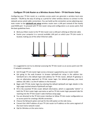
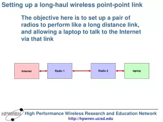
Learn how to set up a pair of radios to create a long-distance link and enable internet access for remote locations, sensors, cameras, and computer access.

E N D
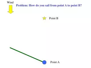
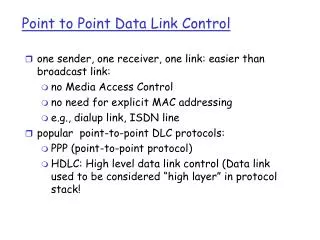
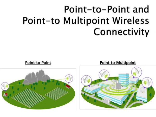
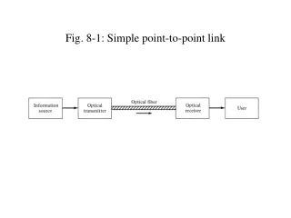
Setting up a long-haul wireless point-point link The objective here is to set up a pair of radios to perform like a long distance link, and allowing a laptop to talk to the Internet via that link Radio 2 laptop Radio 1 Internet
Objective for today Internet access • Remote location: • Sensors • Cameras • Computer access
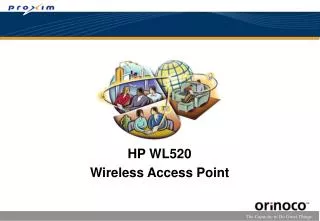
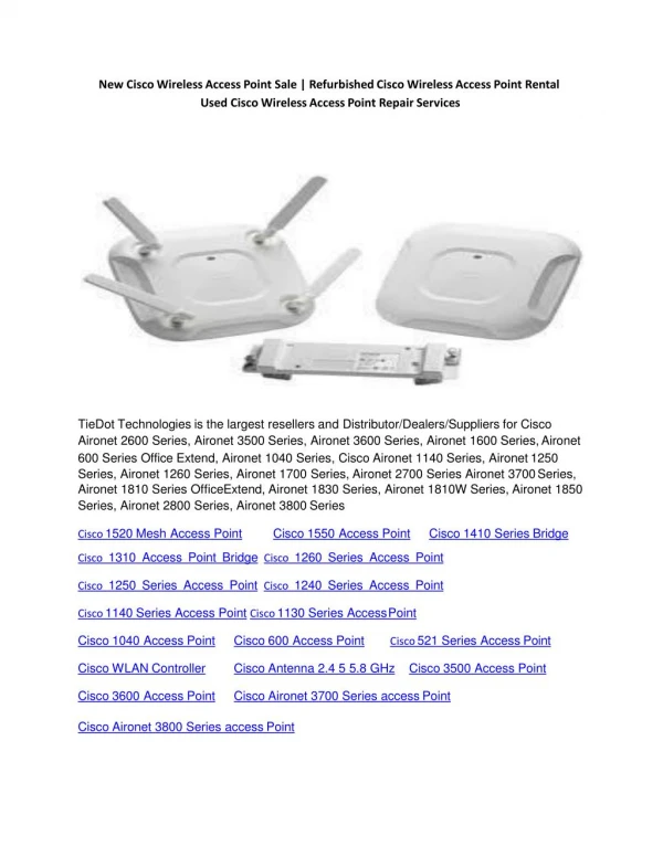
Radios and frequencies This workshop will use a multi-band 5GHz radio for the radio link setup. We will use a Trango Broadband radio. This representative selection is for demonstration purposes only, since HPWREN uses quite a few of those. There are many other radio choices, and the concepts used are similar.
Internet addresses • Similar to telephone numbers (area code + local number) • Internet address = Network number + Host • Consist of four 0…255 numbers (bytes), like 172.23.223.102 • Net/Host differentiated by a binary mask, like 255.255.255.0 • Also needed is a “default gateway” to connect to other nets • Example: • 172.23.223.102 Internet address • 255.255.255.0 Network mask • 172.23.223.1 Default gateway • Names, like www.nps.gov, are translated to IP addresses via the Domain Name System (DNS)
Internet addresses • For this workshop only: • Use 172.16.223.100 for one end radio • Use 172.16.223.101 for the other radio • Use 255.255.255.0 for the network address mask • which is: 11111111 11111111 11111111 00000000 • Use 172.16.223.1 for the default gateway
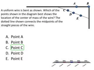
Signal strength and polarity • Directional antennas focus the radio signal beam, • not unlike a flashlight with a reflector appearing brighter • Polarization defines how the signal propagates, • not unlike a swinging rope being able to polarize • transmitter and receiver needs to use the same polarization • Signal strength is measured on a logarithmic scale • 1 dBm = 1 milliwatt • add 3dB for every doubling of the signal strength (antenna?) • subtract 3dB for 50% less signal strength (signal loss?) • often -70dBm to -30dBm are good receive signal levels • depends on the product being used….
Signal strength • Things that increase signal strength • more radio output power • directional antenna • Things that decrease signal strength • distance between radios • antenna cables • antenna cable connectors • bad weather • Things that can do either • inversion layers • signal reflections
Radio signal emissions Do not install radios in locations where anyone gets exposed to prolonged radio emissions over short distances
Things to configure in radios • Internet addresses, subnet mask, default gateway • some radios need to specify Master vs. Remote • remote radio/link identification (e.g., peerid) • radio frequency • antenna polarization • radio transmit power • network speed, and whether it is adaptive • link encryption • passwords • enable/disable link retransmissions • miscellaneous things (e.g., opmode, defaultopmode)
Example radio configuration • Internet address: ipconfig 172.16.223.100 255.255.255.0 172.16.223.1 • Radios Master vs. Remote: utype mu vs. utype ru • radio/link identification: peerid 11223344 • radio frequency and polarization: freq 14 h • radio transmit power: power 17 • network speed, and whether it is adaptive: speed 54 • autorateshift on • link encryption: encrypt on • encrypt key 1111 2222 3333 4444 5555 6666 7777 8888 • passwords: password rw and nps • enable/disable link retransmissions: arq on • miscellaneous things (e.g., opmode, defaultopmode): opmode on
Example radio configuration • Trango radios usually ship with IP address 192.168.100.100 • Start new configuration by setting a computer to something similar, • like 192.168.100.101 On Master radio (1): telnet 192.168.100.100 trango ipconfig 172.16.223.100 255.255.255.0 172.16.223.1 utype mu peerid DE1C3FE1 freq 2 v (“freq 14 h” for the outside setup) defaultopmode on opmode on power 2 autorateshift on encrypt on encrypt key 1111 2222 3333 4444 5555 6666 7777 8888 password rw npswkshp On Remote radio (2): telnet 192.168.100.100 trango ipconfig 172.16.223.101 255.255.255.0 172.16.223.1 utype ru peerid DE1C41DF freq 2 v (“freq 14 h” for the outside setup) defaultopmode on opmode on power 2 autorateshift on encrypt on encrypt key 1111 2222 3333 4444 5555 6666 7777 8888 password rw npswkshp
Configured radio example Trying 172.16.223.100... Connected to npswkshp-tl45-master. Escape character is '^]'. Welcome to Trango Broadband Wireless, Atlas PtP-P5010M 1p2r7D06040601 Password: Login as read/write. #> sysinfo ********************************* 0 ********************************* [Model] P5010M (EXT) [Unit Type] MU [Hardware Version] 5010 [Firmware Version] 1p2r7D06040601 [System Up Time] 0 day(s) 00:28:55 ********************************* 1 ********************************* [MAC] 00 01 DE 1C 41 DF [S/N] 1851871 [IP] 172.16.223.100 [Subnet Mask] 255.255.255.0 [Gateway] 172.16.223.1 ********************************* 2 ********************************* [Radio Temp] 31 C [PoE Voltage] 23.9 V [Opmode] on [Default Opmode] on [Active Channel] 2 v [Freq] 5280 MHz [Speed] 54 Mbps [Tx Power] 2 dBm [Power Range] -4..7 dBm [Peer ID] DE1C3FE1 [Status] connected [RSSI] -58 dBm [Peer IP Config] 172.16.223.101 255.255.255.0 172.16.223.1 ********************************* 3 ********************************* Channel Table: (MHz, n/a: not available in current area) [Ch#01] 5260 [Ch#02] 5280 [Ch#03] 5300 [Ch#04] 5320 [Ch#05] 5325 [Ch#06] 5480 n/a [Ch#07] 5500 n/a [Ch#08] 5520 n/a [Ch#09] 5540 n/a [Ch#10] 5560 n/a [Ch#11] 5580 n/a [Ch#12] 5600 n/a [Ch#13] 5620 n/a [Ch#14] 5640 n/a [Ch#15] 5660 n/a [Ch#16] 5680 n/a [Ch#17] 5700 n/a [Ch#18] 5720 n/a [Ch#19] 5735 [Ch#20] 5755 [Ch#21] 5775 [Ch#22] 5795 [Ch#23] 5815 [Ch#24] 5835 ********************************* 4 ********************************* [Area Code] 0 RF Band #1 (5180..5240 MHz) Disabled RF Band #2 (5260..5325 MHz) [Power Range] -4..7/7/7/7 dBm RF Band #3 (5480..5720 MHz) Disabled RF Band #4 (5735..5835 MHz) [Power Range] -4..21/19/18/17 dBm ********************************* 5 ********************************* [Tx MIR] 50000 Kbps [ARQ] on [Encrypt] on [Key] 1111 2222 3333 4444 5555 6666 7777 8888 [Auto Rate Shift] on [RSSI LED] on [Remarks] Remarks ********************************* 6 ********************************* [Eth Config] ANEG [Eth Status] 0 HDX [Eth In] 1,278,949 bytes 0 Kbps [Eth Out] 21,427 bytes 0 Kbps [RF In] 1,950,904 bytes 32 Kbps [RF Out] 11,280 bytes 2 Kbps [ARQ Retransmission] 1 pkts Success. #> exit Connection closed by foreign host.