Download
1 / 8
80 likes | 324 Views
CS232 Midterm Exam 2 October 29, 2004. Name: Section: This exam has 8 pages (including a cheat sheet at the end). Read instructions carefully! You have 50 minutes, so budget your time! No written references or calculators are allowed.

E N D
CS232 Midterm Exam 2 October 29, 2004 Name: Section: This exam has 8 pages (including a cheat sheet at the end). Read instructions carefully! You have 50 minutes, so budget your time! No written references or calculators are allowed. To make sure you receive credit, please write clearly and show your work. We will not answer questions regarding course material.
Question 1: Performance (25 points) Consider the single-cycle and multi-cycle implementations discussed in lecture (for your reference the datapath for the single cycle is provided on the last page of this exam, the multi-cycle datapath and control are provided on pages 4 and 5, respectively). Given the functional unit latencies shown on the right, answer the following questions. Part (a) What is the (minimum) cycle time for the single cycle implementation? Explain. (5 points) The cycle time must be long enough to accommodate the slowest instruction, lw. lw uses memory twice, the ALU once, and the reg. file twice; 4+2+3+4+2 = 15ns. Part (b) What is the (minimum) cycle time for the multi-cycle implementation? Explain. (5 points) Now the cycle time must be long enough to accommodate the slowest functional unit. In this case, that’s the memory. The cycle time must thus be at least 4ns. Below are two equivalent versions of C code for a loop that scales each element of a vector by a variable s. The version on the right uses array indexing, and the version on the left uses pointer arithmetic. for (int i = 0 ; i < L ; ++ i) { for (int i = 0 ; i < L ; ++ i) { D[i] = s * A[i] *D = s * (*A); A++; D++; } } Below is MIPS assembly code that corresponds to the pointer arithmetic version: loop: lw $t0, 0($a0) # (*A) mul $t0, $t0, $a3 # s * (*A) sw $t0, 0($a1) # *D = s * (*A) add $a0, $a0, 4 # A ++ add $a1, $a1, 4 # D ++ add $t1, $t1, 1 # ++ I blt $t1, $t2, loop # branch to loop if (i<L) Part (c) How many cycles would one iteration of this loop take to execute on the single cycle datapath? (5 points) Each instruction takes one cycle. There are 7 instructions, so one iteration takes 7 cycles. Part (d) How many cycles would one iteration take on the the multicycle datapath? Assume the mul is as fast as an add and a blt is the same as a beq. (10 points) Now lw takes 5 cycles, mul takes 4, sw takes 4, add takes 4, and blt takes 3. In total, the loop takes 5 + 4 + 4 + 4 + 4 + 4 + 3 = 28 cycles.
Question 2: Multi-cycle CPU implementation (55 points) Some ISA’s have support for memory instructions with post-increment. These instructions perform both a load (or store) and an add to the address register. The value added to the address register is the size of the operand loaded/stored. For example: lw+ $t0, 0($a0) encodes lw $t0, 0($a0) add $a0, $a0, 4 and sw+ $t0, 0($a1) encodes sw $t0, 0($a1) add $a1, $a1, 4 These instructions are useful for loading/storing to values in arrays. For example, the code on the previous page could be reduced to: loop: lw+ $t0, 0($a0) # (*A); A++ mul $t0, $t0, $a3 # s * (*A) sw+ $t0, 0($a1) # *D = s * (*A); D ++ add $t1, $t1, 1 # ++ I blt $t1, $t2, loop # branch to loop if (i<L) On the next page, we’ll consider how to implement these instructions in the multi-cycle implementation.
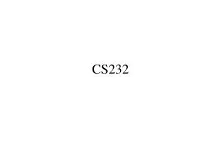
Shift left 2 ALU Out ALU Zero 0 1 2 3 Result ALUOp Memory data register ALUSrcB Sign extend PCWrite ALUSrcA PC IorD 0 M u x 1 RegDst RegWrite MemRead 0 M u x 1 0 M u x 1 Read reg 1 Read data 1 A Address IRWrite B Read reg 2 Memory Read data 2 0 M u 2 1 Write register PCSrc [31-26] [25-21] [20-16] [15-11] [15-0] 4 Write data Mem Data Register file Write data MemWrite Instr register 0 M u x 1 Question 2, continued The lw+ and sw+ instructions have the same format i-type as lw and sw, shown below. Recall that in a load the rt field designates the destination register for the load. lw+ rt, offset(rs) # R[rt] = Memory[R[rs]+offset]; R[rs] += 4; sw+ rt, offset(rs) # Memory[R[rs]+offset] = R[rt]; R[rs] += 4; Part (a) The multicycle datapath from lecture appears below. Show what changes are needed to support lw+ and sw+. You should only add wires and muxes to the datapath; do not modify the main functional units themselves (the memory, register file, and ALU). Try to keep your diagram neat! (10 points) Note: While we’re primarily concerned about correctness, five (5) of the points will only be rewarded to solutions that use a minimal number of cycles and do not lengthen the clock cycle. Assume that everything besides the ALU, Memory and Register file is instantaneous. Don’t worry about minimizing the number of states. Note that lw+ and sw+ work just like lw and sw, except that we need to add to rs. Our datapath already supports lw and sw, so we just need to make sure it lets us add to rs. To do this, we extend the RegDst mux. MemToReg
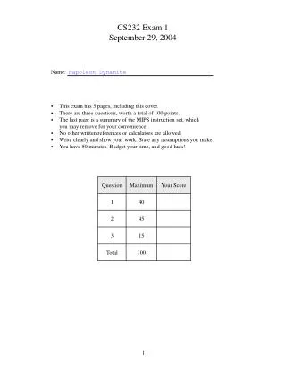
IorD = 0 MemRead = 1 IRWrite = 1 ALUSrcA = 0 ALUSrcB = 01 ALUOp = ADD PCSource = 0 PCWrite = 1 RegDst = 0 MemToReg = 1 RegWrite = 1 ALUSrcA = 1 ALUSrcB = 1 ALUOp = ADD IorD = 1 MemWrite = 1 ALUSrcA = 1 ALUSrcB = 1 ALUOp = ADD ALUSrcA = 1 ALUSrcB = 00 ALUOp = SUB PCSource = 1 PCWrite = Zero ALUSrcA = 1 ALUSrcB = 00 ALUOp = func ALUSrcA = 1 ALUSrcB = 10 ALUOp = ADD ALUSrcA = 1 ALUSrcB = 10 ALUOp = ADD ALUSrcA = 1 ALUSrcB = 10 ALUOp = ADD RegDst = 10 MemToReg = 0 RegWrite = 1 RegDst = 0 MemToReg = 1 RegWrite = 1 Question 2 continued Part (b) Complete this finite state machine diagram for the lw+ and sw+ instruction. Control values not shown in each stage are assumed to be 0. Remember to account for any control signals that you added or modified in the previous part of the question! (25 points) Branch completion Instruction fetch and PC increment Register fetch and branch computation Op = BEQ ALUSrcA = 0 ALUSrcB = 11 ALUOp = ADD R-type execution Write- back Op = R-type RegDst = 1 MemToReg = 0 RegWrite = 1 Op = SW+ Op = LW+ Effective address computation Memory write Op = LW/SW IorD = 1 MemWrite = 1 Op = SW Op = LW lw register write Memory read IorD = 1 MemRead = 1 IorD = 1 MemRead = 1 For the most part, lw+ and sw+ behave just like the normal lw and sw. For each instruction, we add an extra cycle at the end to update the value of rs. Additionally, we calculate rs + 4 in the next-to-last cycle for each instruction.
Question 2 continued Part (c) What is the average CPI of the new version of code on your modified data path. You can leave your result as an expression. State any assumptions. (10 points) Under our implementation, lw+ takes 6 cycles and sw+ takes 5. mul, add, and blt are unchanged. The number of cycles needed for one iteration of the loop is thus 6 + 4 + 5 + 4 + 3 = 22 cycles. Each iteration has 5 instructions, so the CPI is 22/5. Part (d) A fellow engineer proposes spending two cycles for each memory access, to allow the clock period to be shortened. This would add 2 cycles (one for each memory access) to the execution of each load and store and one cycle to each non-memory instruction. Would this improve the execution time of the second version of the loop (found on page 3). Show your work. (10 points) If we split the memory access into two parts, then the clock period is now limited by the ALU latency. Therefore, the new clock period is 3ns. Now, lw+ takes 8 cycles, sw+ takes 7, mul takes 5, add takes 5, and blt takes 4. Each iteration of the loop now takes 8 + 5 + 7 + 5 + 4 = 29 cycles. Under the old system, the loop took 22 cycles * 4ns/cycle = 88ns to execute. Under the new system, the loop takes 29 cycles * 3ns/cycle = 87ns to execute. Execution time improves, but just barely.
Question 3: Conceptual Questions (20 points) Write a short answer to the following questions. For full credit, answers should not be longer than three sentences. Part (a) In what circumstances is throughput the desired performance metric and in what circumstances is latency the desired metric? (10 points) Throughput is a useful metric when you’re concerned about how much work can get done in a set amount of time; for example, throughput is important for servers or clusters. Latency is useful when you’re concerned about how long it takes to do one thing; for example, latency is important for systems that need a short response time, such as home PCs or embedded devices. Part (b) Which of the three factors of CPU time can a compiler influence? Provide examples. (10 points) # of instructions – yes; for example, loop unrolling reduces the number of instructions executed. CPI – yes; for example, good register allocation can eliminate unnecessary loads and stores. Since loads take a relatively high number of cycles, reducing the relative frequency of loads will reduce the CPI. clock period – no; the clock period is entirely dependent upon the hardware. Do not write in shaded region
0 M u x 1 Add PC 4 Add Shift left 2 PCSrc RegWrite MemToReg MemWrite Read address Instru- ction [31-0] I [25 - 21] Read register 1 Read data 1 ALU Read address Read data 1 M u x 0 I [20 - 16] Zero Read register 2 Instruction memory Read data 2 0 M u x 1 Result Write address 0 M u x 1 Write register Data memory Write data Registers I [15 - 11] ALUOp Write data MemRead ALUSrc RegDst I [15 - 0] Sign extend Single Cycle Datapath: Performance 1. Formula for computing the CPU time of a program P running on a machine X: CPU timeX,P = Number of instructions executedP x CPIX,P x Clock cycle timeX 2. CPI is the average number of clock cycles per instruction: CPI = Number of cycles needed ⁄ Number of instructions executed 3. Speedup is a metric for relative performance of 2 executions: Speedup = Performance after improvement ⁄ Performance before improvement = Execution time before improvement / Execution time after improvement